Tool capable of applying pressure to carry out electron beam auxiliary heat action connection

A technology of applying pressure and electron beam, which is applied in the direction of electron beam welding equipment, auxiliary welding equipment, auxiliary devices, etc.

Inactive Publication Date: 2013-04-03
HARBIN INST OF TECH
View PDF5 Cites 3 Cited by
  • Summary
  • Abstract
  • Description
  • Claims
  • Application Information

AI Technical Summary

Problems solved by technology

However, the existing high-energy welding equipment is not equipped with corresponding pressure-applying auxiliary clamping tools. The present invention is a small welding auxiliary clamping tool, which can realize lo

Method used


Image

  • Tool capable of applying pressure to carry out electron beam auxiliary heat action connection
  • Tool capable of applying pressure to carry out electron beam auxiliary heat action connection
  • Tool capable of applying pressure to carry out electron beam auxiliary heat action connection

Examples


specific Embodiment approach 1

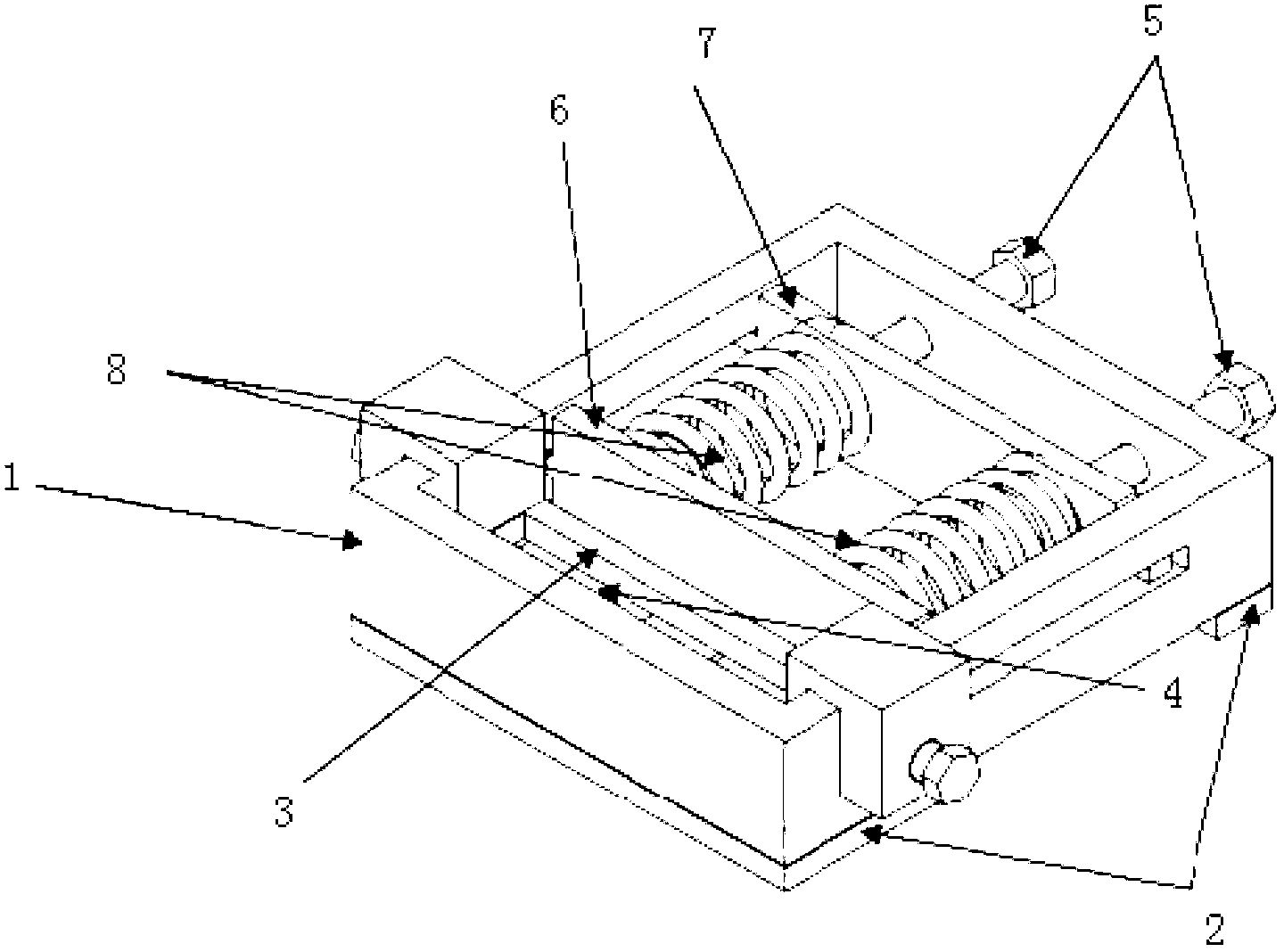
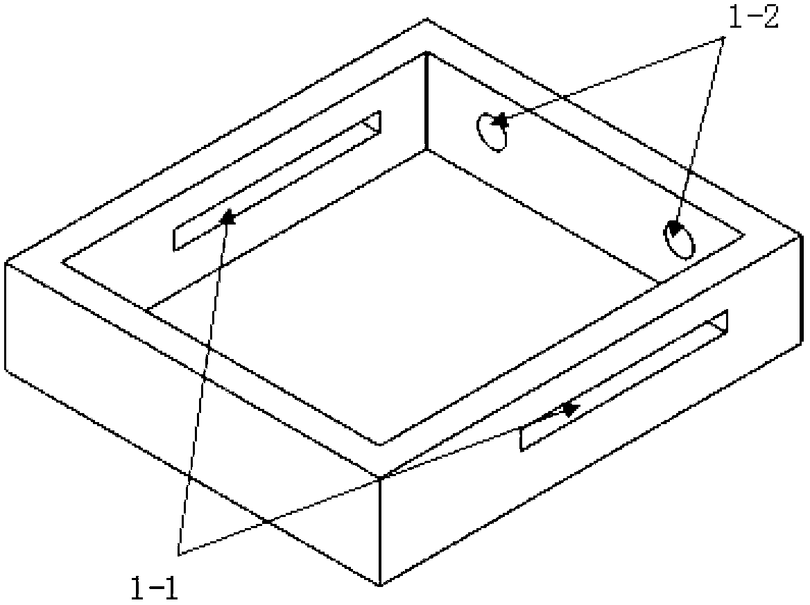
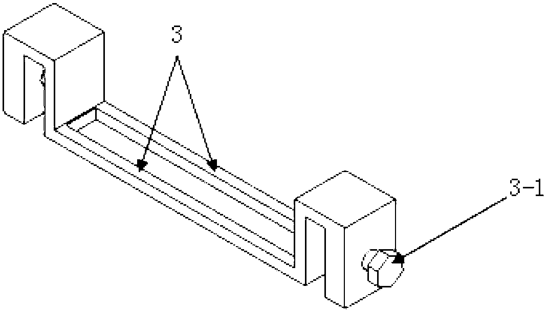
[0019] Embodiment 1: A tool capable of applying pressure for electron beam assisted thermal connection in this embodiment is composed of a clamp shell 1, a clamp base 2, a vertical fixing device and a horizontal fixing device, wherein the clamp shell 1 is fixedly connected On the fixture base 2, two opposite side walls of the fixture shell 1 are provided with sliding guide grooves 1-1, and the rear wall of the fixture shell 1 is provided with limiting holes 1-2, and the vertical fixing device is arranged on the fixture shell 1 The internal front end, the vertical fixing device is composed of a vertical fixing rod 3 and a bottom backing plate 4, the two ends of the vertical fixing rod 3 are engaged with the two side walls of the fixture shell 1 by fastening screws 3-1, and the bottom backing plate 4 is set Directly below the vertical fixing rod 3, wherein, the bottom backing plate 4 is provided with two raised fixing bars 4-1 and is opposite to the vertical fixing rod 3. The fi...

specific Embodiment approach 2

[0030] Embodiment 2: This embodiment is different from Embodiment 1 in that: the main material of the fixture shell 1 is stainless steel without ferromagnetism. Other steps and parameters are the same as those in Embodiment 1.

specific Embodiment approach 3

[0031] Embodiment 3: This embodiment differs from Embodiment 1 or Embodiment 2 in that the clamp base 2 is made of non-ferromagnetic 6061 aluminum alloy. Other steps and parameters are the same as those in Embodiment 1 or Embodiment 2.


PUM

PropertyMeasurementUnit
Lengthaaaaaaaaaa
Elastic coefficientaaaaaaaaaa

Abstract

The invention relates to a tool capable of applying a pressure to carry out electron beam auxiliary heat action connection. The invention relates to a welding fixture for an electron beam auxiliary heat source action connection method. The invention aims to solve the problems of serious metal fire waste, interface reaction and the like, which are generated when a conventional fusion welding technology is adopted to process certain materials, so as to provide the tool capable of applying the pressure to carry out electron beam auxiliary heat action connection. The tool capable of applying the pressure to carry out electron beam auxiliary heat action connection is formed by a fixture housing, a fixture base, a vertical fixing device and a horizontal fixing device. The tool has the following working principle that the welding fixture disclosed by the invention is used by applying a certain pressure to a contact surface of a base metal, simultaneously utilizing a defocused electron beam to carry out circular scanning on a weld joint, repeatedly scanning in a reciprocating manner and controlling the welding speed so as to implement effects of raising the welding temperature and prolonging the heat preservation time, i.e. the defocused electron beam is used as a heat source to implement local connection of the base metal. The tool belongs to the field of a welding auxiliary tool.

Description

technical field [0001] The invention relates to a welding fixture for an electron beam assisted heat source action connection method, which belongs to the field of welding auxiliary tools. Background technique [0002] For some materials, such as composite materials, it is difficult to achieve excellent connection effects by traditional fusion welding methods, which will cause serious metal burning and interface reactions. In addition to heating the parts, it is also necessary to heat the weldment as a whole, which will exert additional heat on the base metal of the weldment and affect the overall performance of the base metal. Therefore, it is considered to only carry out local thermal action connection on the welded joints, without welding and heating the base metal as a whole. This requires the use of high-energy-density welding methods with small heat source action areas, such as laser welding and electron beam welding. However, the existing high-energy welding equipmen...

Claims


Application Information

Patent Timeline
IPC IPC(8): B23K37/04B23K15/00
Inventor 陈国庆张秉刚王廷冯吉才甄公博
Owner HARBIN INST OF TECH
Why Eureka
Try Eureka