Solder strip traction device for crystalline silicon solar cell module and positioning and welding methods

A solar cell, solar cell technology, applied in electrical components, welding equipment, laser welding equipment, etc., can solve the problems of the offset of the welding strip and the main grid, welding failure, difficult to fix, etc., to improve welding efficiency and welding effect. , to ensure accurate positioning, convenient welding effect

Active Publication Date: 2020-08-14
帝尔激光科技(无锡)有限公司
View PDF10 Cites 6 Cited by
  • Summary
  • Abstract
  • Description
  • Claims
  • Application Information

AI Technical Summary

Problems solved by technology

[0004] But this method also has some problems
For the traditional 5BB ribbon, which is a flat ribbon, after laying on the surface of the cell, it only depends on its own weight and the weight of the cell to ensure positioning, which is extremely difficult and has poor reliability.
For multi-busbar (MBB) cells, since the ribbons are multiple circular ribbons, after they are laid on the surface of the cell, it is difficult to keep their positions fixed with the position of the main grid of the cell, which will cause welding problems during welding. Ribbon offset from busbar, resulting in soldering failure or scrap

Method used


Image

  • Solder strip traction device for crystalline silicon solar cell module and positioning and welding methods
  • Solder strip traction device for crystalline silicon solar cell module and positioning and welding methods
  • Solder strip traction device for crystalline silicon solar cell module and positioning and welding methods

Examples


Embodiment Construction

[0033] The present invention will be further described below in conjunction with specific examples and accompanying drawings.

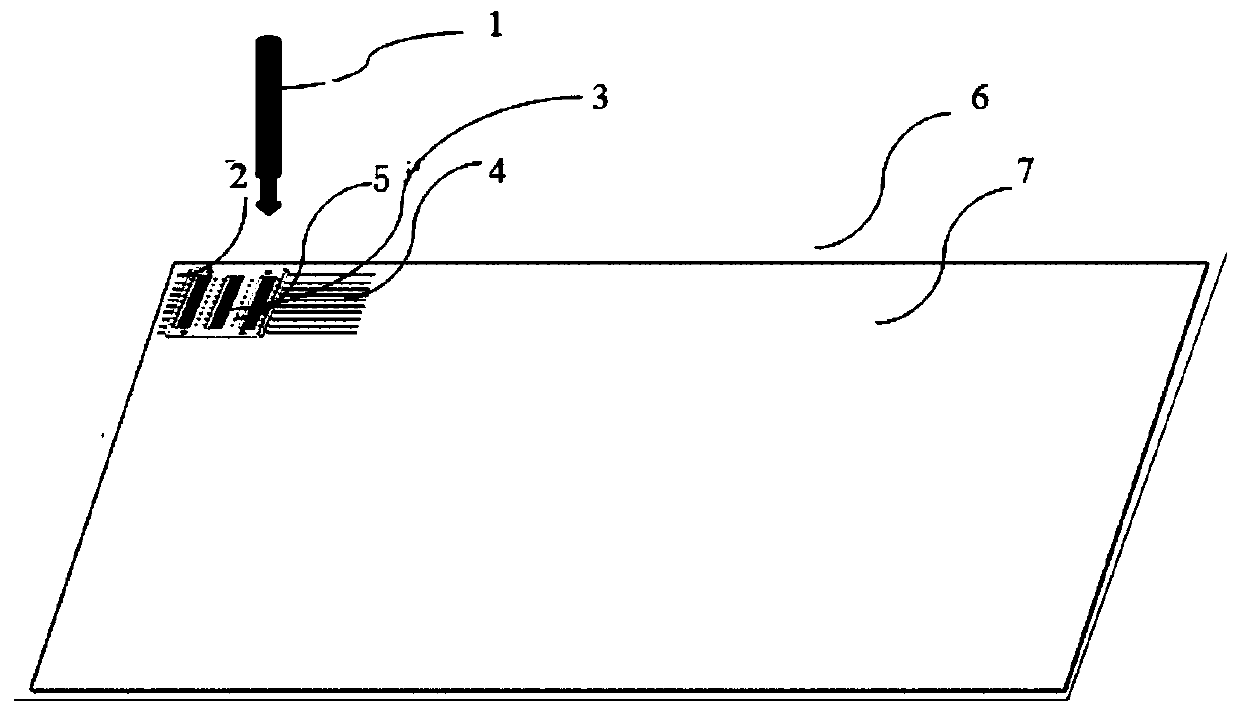
[0034] Such as figure 1 Shown, the present invention provides a kind of ribbon welding method of crystalline silicon solar cell module, comprises the following steps:

[0035] L1, place the bottom layer, the bottom layer includes a transparent rigid plate 6, such as flat glass, so that light is transmitted when laser welding is carried out, the bottom layer can also include a transparent elastic plate 7 arranged on the transparent rigid plate 6, such as an EVA sheet, the transparent The elastic plate 7 can make light transmittance during welding, and at the same time avoid fragments caused by the rigid pressure on the solar cells 3 after vacuuming.

[0036] L2. Locate the bottom welding ribbon 2, the solar battery sheet 3 and the surface welding ribbon 4 according to the ribbon positioning method. The bottom welding strip 2 or the surface welding st...


PUM


Abstract

The invention provides a solder strip traction device for a crystalline silicon solar cell module and positioning and welding methods. At least one bottom face solder strip is carried and placed on abottom layer according to preset positions; solar cells are carried and placed on the bottom face solder strips according to preset positions; at least one surface solder strip is carried and placed on the solar cells according to preset positions, and the surface solder strips are located over the corresponding bottom face solder strips; and local fixation on at least one point is carried out onthe surface solder strips, the solar cells and the corresponding bottom face solder strips in the length direction of the surface solder strips through hollowed-out parts on a negative pressure sucker. The hollowed-out solder strip traction device is designed, the solder strips can be directly sucked to be placed on main grid lines of the solar cells, glue dispensing or non-contact type solderingcan be carried out on one or more points of the solder strips through the hollowed-out parts, accurate positioning of the soldering strips and the main grid lines can be effectively ensured, interconnecting strips before soldering and moving of the grid lines of the cells can be avoided, and the welding efficiency and the welding effect can be improved.

Description

technical field [0001] The invention belongs to the technical field of photovoltaic manufacturing and application, and in particular relates to a ribbon pulling device and a positioning and welding method for a crystalline silicon solar cell module. Background technique [0002] The production of solar cell modules is the process of stringing and welding solar cells. The existing traditional battery string welding needs to use a pressure pin to press the welding strip, so that the welding strip can be welded in a proper position during welding, and ensure that the welding strip is attached to the surface electrode of the battery to ensure the welding effect. The welding process in which the pressure pin presses the ribbon and the slight vibration of the battery sheet and the ribbon in the subsequent arrangement during the forward transmission process may cause subtle cracks. [0003] A new manufacturing method of the solar battery module reduces the hidden cracks that may b...

Claims


Application Information

Patent Timeline
Patent Type & Authority Applications(China)
IPC IPC(8): B23K26/21B23K26/70H01L31/18
CPCB23K26/21B23K26/702H01L31/188Y02E10/50Y02P70/50
Inventor 李志刚覃榆森朱凡朱胜鹏陆红艳
Owner 帝尔激光科技(无锡)有限公司
Why Eureka
Try Eureka