Automatic intermittent cycle worktable

A workbench and automatic technology, applied in the direction of manufacturing tools, metal processing equipment, metal processing machinery parts, etc., can solve the problems of inability to adjust, difficult indexing accuracy, high indexing accuracy, etc., to reduce labor force, strong applicability, Versatile effect

Inactive Publication Date: 2013-04-03
福鼎市金雄机车部件有限公司
View PDF5 Cites 6 Cited by
  • Summary
  • Abstract
  • Description
  • Claims
  • Application Information

AI Technical Summary

Problems solved by technology

[0003] The disadvantage of this structure is that the indexing angle of equal division is a fixed value, and the indexing accuracy is high and cannot be adjusted. When a large workpiece is operated in multiple positions, the corresponding diameter of the disc also needs to be relatively large, which is difficult to manufacture and the indexing accuracy cannot be adjusted. It is also difficult to ensure that the space of the working position is limited, and the adjacent stations often interfere with each other, which limits the scope of use to a certain extent.

Method used


Image

  • Automatic intermittent cycle worktable
  • Automatic intermittent cycle worktable
  • Automatic intermittent cycle worktable

Examples


Embodiment 1

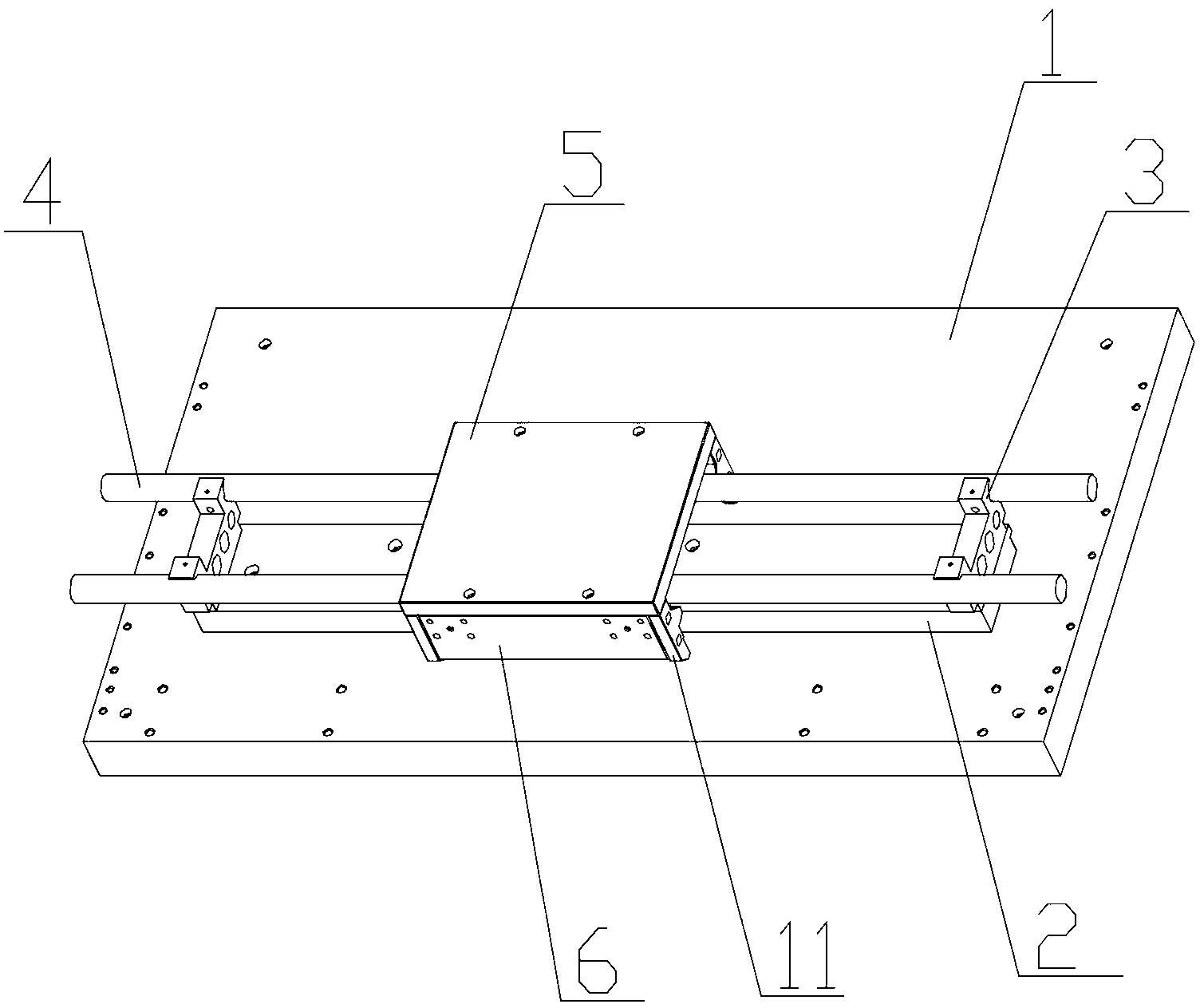
[0039] Such as Figure 19 , is the automatic intermittent cycle workbench of the present invention, the automatic intermittent cycle workbench is an up and down cycle structure,

[0040] Including guide rail and sliding table combination device 100, pneumatic pulling and pushing device assembly 200, working sliding table movement limit device 300, sliding table return device 400 and upper and lower track running device 500, each guide rail and sliding table combination device 100 are equipped with a pneumatic pulling and pushing device assembly 200 and a working sliding table movement limit device 300, and the pneumatic pulling and pushing device assembly 200 is used to control the movement of the sliding table of the guide rail and sliding table combination device 100 on the guide rail. Movement; the moving limit device 300 of the working slide table is used to control the limit when the slide table of the guide rail and slide table combination device 100 moves to the working...

Embodiment 2

[0063] Such as Figure 15 , is another scheme of the automatic intermittent cycle workbench described in the present invention, the automatic intermittent cycle workbench is a planar cycle structure, adopts an even number of guide rail and slide table combination devices 100 arranged in parallel to each other, and is installed on the guide rail and slide table The lower pneumatic pulling and pushing device assembly 200 of the combination device 100 and the working sliding table movement limit device 300 together form a horizontal track device, and the two ends of the horizontal track device are respectively connected with vertical tracks that can be connected to it The device 600 forms a docked horizontal circular revolving track, and the vertical track device includes a horizontal slide table and a guide rail conveying device 601 and a secondary guide rail device 602, and a secondary guide rail device 602 is fixedly installed on the horizontal slide table and the guide rail co...

Embodiment 3

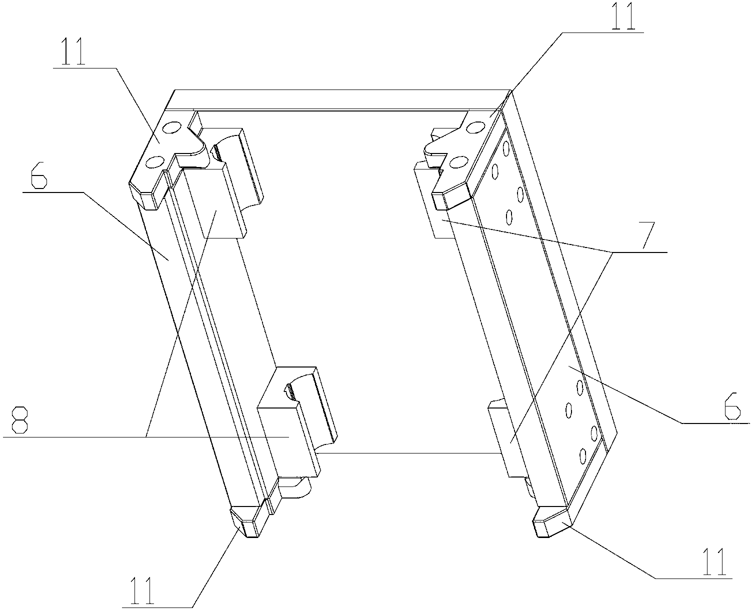
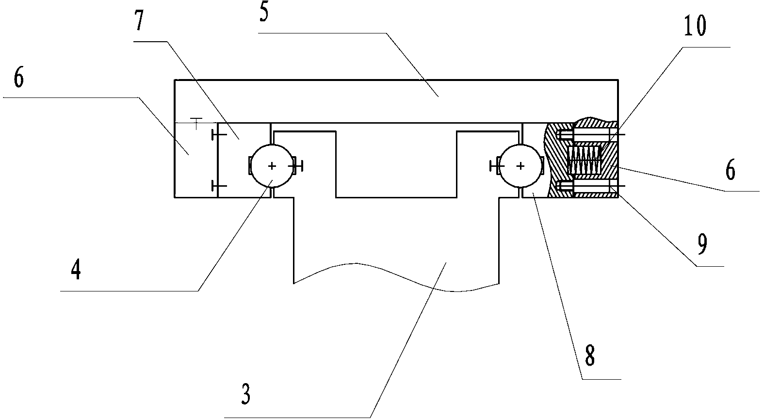
[0068] Such as Figure 17 and 21 , is another scheme of the automatic intermittent cycle workbench described in the present invention, the described automatic intermittent cycle workbench is a device when a single workbench works in an independent cycle, and several groups of guide rail and sliding table combination devices 100, Pneumatic pulling and pushing device assembly 200, working sliding table movement limiting device 300, wherein guide rail and sliding table combination device 100, pneumatic pulling and pushing device assembly 200, working sliding table moving limiting device 300 are basically the same, the difference The position is to first confirm the groove of the fixed block 17 on the pneumatic pulling and pushing device assembly, which is located at the top during installation, and then remove a positioning block 11 close to the cylinder 12 from the slide table on the same side of the fixed block 17 , the positioning block 11 is used as a protruding part of the ...


PUM


Abstract

The invention relates to an automatic intermittent cycle worktable. The automatic intermittent cycle worktable comprises at least two guide rail and sliding table combination devices which form a group, pneumatic pulling and pushing device assemblies which are matched with the guide rail and sliding table combination devices, and work sliding table movement limiting devices, wherein the pneumatic pulling and pushing device assemblies are arranged below the guide rail and sliding table combination devices and are used for controlling the movement of each sliding table on each guide rail; and the work sliding table movement limiting devices are arranged below the guide rail and sliding table combination devices, and are used for controlling the limiting when each sliding table is moved to a work station. By using the automatic intermittent cycle worktable, the number of worktables can be increased or reduced as required; the automatic intermittent cycle worktable is adjusted and positioned freely, easy to operate, high in universality, and cycled automatically; the labor force is reduced; and the automatic intermittent cycle worktable can be switched into an independent cycle work of a single worktable as required, high in practicability and can be used in a plurality of industries.

Description

Technical field [0001] The present invention involves mechanical automation circulation devices, especially a intermittent automation circulation device using cylinder push -pull binding to the platform and controlling the sliding location. Background technique [0002] Most of the existing mechanical automated intermittent device uses equal division of rotation discs.There are many institutions such as cam, connecting rods, hydraulic, pneumatic, servo or step -by -step motor with a speed device. Most of the structure forms around a central axis, and a fixed equivalent angle is rotated on a disc surface of a disc.Time, do homework, and then rotate another angle, stop for a period of time, and do the operation after week. [0003] The defect of this structure is that the equivalent angle is the fixed value, the accuracy requirements are high, and cannot be adjusted. When the large workpiece and multi -station work, the corresponding diameter of the discIt is also difficult to guar...

Claims


Application Information

Patent Timeline
IPC IPC(8): B23Q1/26
Inventor 林雄
Owner 福鼎市金雄机车部件有限公司
Why Eureka
Try Eureka