Pneumatic composite clamping device

A clamping device and clamping technology, applied in the directions of positioning device, clamping, support, etc., can solve the problems of difficult operation, high cost, complicated device, etc., and achieve the effects of low processing and manufacturing cost, convenient operation and simple structure

Inactive Publication Date: 2013-04-03
符雪
View PDF0 Cites 0 Cited by
  • Summary
  • Abstract
  • Description
  • Claims
  • Application Information

AI Technical Summary

Problems solved by technology

[0003] Although all kinds of clamping devices can meet the requirements of workpiece clamping to a certain extent, because they are non-standard devices, they often need to be designed and manufactured according to product mechanism characteristics, production conditions and actu

Method used


Image

  • Pneumatic composite clamping device

Examples


Embodiment Construction

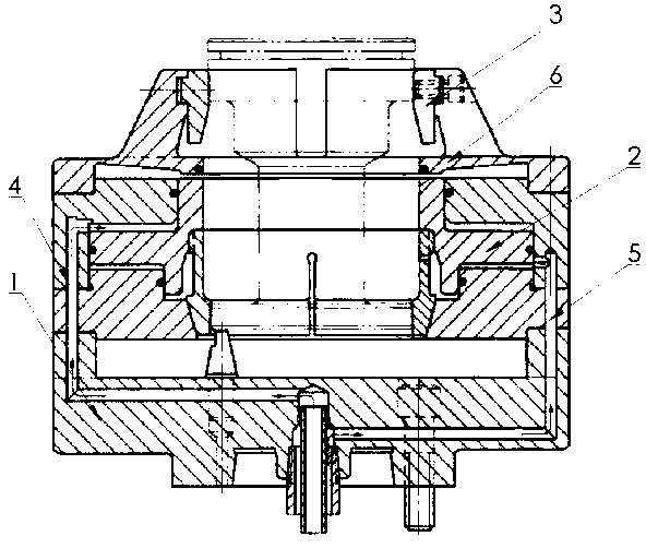
[0010] Below in conjunction with accompanying drawing and embodiment the technical solution of the present invention is further described:

[0011] like figure 1 As shown, the present invention provides a pneumatic composite clamping device, including a base 1 provided with a cylinder, a piston 2 cooperating with the cylinder, a jaw 3 cooperating with the piston 2, and two limit positions of the piston 2 respectively. There are six claws for clamping air passage 4 and releasing air passage 5, which are evenly installed on the prestressed metal sheet 6. The metal sheet 6 is normally concave downwards, so that the claws 3 on its upper surface are in a clamping position. state, the upward limit state of the piston 2 is to squeeze the metal sheet 6 to make the metal sheet 6 protrude upwards to reach another stable state, thereby releasing the claw 3 .

[0012] The above is only the preferred embodiment of the present invention, it should be pointed out that for those skilled in t...


PUM


Abstract

The invention discloses a clamping device, in particular to a pneumatic composite clamping device. The pneumatic composite clamping device comprises a base, a piston, jaws, a clamping airway and a loosening airway, wherein the base is provided with a cylinder; the piston is matched with the cylinder; the jaws are matched with the piston; the clamping airway and the loosening airway are respectively arranged at two limiting positions of the piston; the jaws are uniformly arranged on a prestressed metal sheet; when the metal sheet is in a normal state, the jaws are in a clamping state; and one limit state of the piston is that the metal sheet is squeezed, so that the metal sheet is in the other stable state to loosen the jaw. The pneumatic composite clamping device which adopts the technical scheme disclosed by the invention has a simple structure, is convenient to operate and is low in cost.

Description

technical field [0001] The invention relates to a clamping device, in particular to a pneumatic composite clamping device. Background technique [0002] Generally, during machining, the workpieces to be processed must be fixed, and the clamping device plays a vital role in machining. [0003] Although all kinds of clamping devices can meet the requirements of workpiece clamping to a certain extent, because they are non-standard devices, they often need to be designed and manufactured according to product mechanism characteristics, production conditions and actual needs, and may not be suitable for other clamping devices. Therefore, the development of clamping devices cannot be slack. In addition, many clamping devices now have problems such as complex structure, difficult operation, high requirements for operators, complex devices, and high cost. Contents of the invention [0004] The technical problem to be solved by the present invention is to provide a clamping device ...

Claims


Application Information

Patent Timeline
IPC IPC(8): B23Q3/00
Inventor 符雪
Owner 符雪
Why Eureka
Try Eureka