
Self-tightening type centering drive plate

A self-tightening, Mohs technology, applied in the field of machinery, can solve the problems of low production efficiency, high labor intensity, poor precision, etc., and achieve the effect of high work efficiency, low labor intensity and convenient operation

Inactive Publication Date: 2013-04-03
YANTAI HAIDE MACHINE TOOL
View PDF6 Cites 12 Cited by
  • Summary
  • Abstract
  • Description
  • Claims
  • Application Information

AI Technical Summary

Problems solved by technology

[0003] The invention provides a self-tightening centering dial, which solves the shortcomings of the manual adjustment method in the background technology, such as high labor intensity, poor precision, and low production efficiency

Method used


Image

  • Self-tightening type centering drive plate

Examples


Embodiment Construction

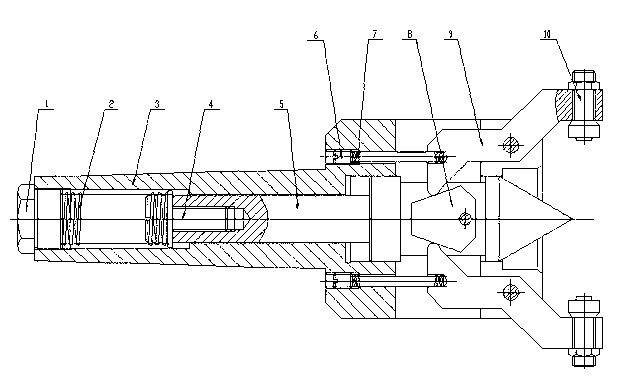
[0009] Below in conjunction with accompanying drawing, the present invention is further described: Self-tightening centering dial, comprises Morse cone 3, is provided with dial top 5 in the Morse cone 3 holes, dial top 5 and Morse cone 3 precision Fitting, the fit gap is 0.005-0.01 mm, the top 5 of the dial is fixedly connected by the adjustment screw 4, the top spring 2 and the compression screw 1, the top 5 of the dial is connected with the floating block 8 through the pin, and the Morse cone 3 passes through Adjusting screw 6, spring 7 and pin are connected with lever pressing plate 9, and the contact of lever pressing plate 9 is in sliding contact with floating block 8, and lever pressing plate 9 is fixedly connected with pressure head 10 by thread.

[0010] Put the Morse cone 3 into the taper hole of the main shaft of the machine tool, place the workpiece between the top of the dial 5 and the top of the tailstock of the machine tool, and the workpiece will be automatically...


PUM


Abstract

The invention provides a self-tightening type centering drive plate. The self-tightening type centering drive plate comprises a Morse cone, wherein a drive plate apex is arranged in the Morse cone; the drive plate apex is fixedly connected through an adjusting screw, a top tension spring and compression screws; the drive plate apex is connected to a floating block through a pin; the Morse cone is connected with a lever pressing plate through another adjusting screw, another spring and another pin; the contact of the lever pressing plate is in sliding contact with the floating block; the lever pressing plate is fixedly connected with a pressing head through a screw thread; and the drive plate apex precisely matches the Morse cone, and the fit clearance is 0.005-0.01 mm. The self-tightening type centering drive plate, disclosed by the invention, has the advantages of operation convenience, high precision, low labor intensity and high working efficiency; and the longitudinal separation of a tail seat is only necessary to adjust when work-pieces with different lengths are machined.

Description

technical field [0001] The invention belongs to the mechanical field, in particular to a self-tightening centering dial. Background technique [0002] When turning workpieces with lathes, there is no special tooling. Generally, the following methods are used: use a clamp to cover the outer surface of the workpiece to be processed, and the clamp has a tightening screw to tighten on the outer surface of the workpiece. The force makes the workpiece and the clamp connect as a whole. The workpiece is mounted on the top of the machine tool bed and tailstock. The jacking screw is moved by the lever at the top of the bed, so that the workpiece is rotated and processed. When loading and unloading, each workpiece All will be tightened or loosened with screws one by one, so the operation is labor-intensive, and the precision is poor, and the production efficiency is low. Contents of the invention [0003] The invention provides a self-tightening centering dial, which solves the disa...

Claims


Application Information

Patent Timeline
Patent Type & Authority Applications(China)
IPC IPC(8): B23Q3/12
Inventor 王允文张爱国
Owner YANTAI HAIDE MACHINE TOOL
Learn More