
electrical tools

A technology for power tools and power components, applied in the field of impact power tools, can solve the problems of large friction resistance of the output shaft, low production cost, high manufacturing and processing level, etc. Effect

Inactive Publication Date: 2016-04-27
NANJING CHERVON IND
View PDF8 Cites 0 Cited by
  • Summary
  • Abstract
  • Description
  • Claims
  • Application Information

AI Technical Summary

Problems solved by technology

[0003] At present, there are two general solutions. One is to improve the machining accuracy and reduce the serial motion gap before and after the output shaft, so that it can be closely matched with the main shaft and the gearbox housing. Although this method solves the problem of the serial motion of the output shaft And it can ensure the efficient rotation of the output shaft, but its processing cost is high and requires a high level of manufacturing and processing; the other is to place a buffer gasket between the main shaft and the output shaft or between the output shaft and the gearbox housing. This method can also solve the problem of the front and rear serial movement of the output shaft, and the production cost is low, but because the output shaft is in close contact with the buffer gasket, it will inevitably bring greater frictional resistance to the rotation of the output shaft, thus affecting the rotation of the output shaft. Rotation efficiency

Method used


Image

  • electrical tools
  • electrical tools
  • electrical tools

Examples


Embodiment Construction

[0022] In order to better understand the technical content of the present invention, specific embodiments are given and described as follows in conjunction with the accompanying drawings.

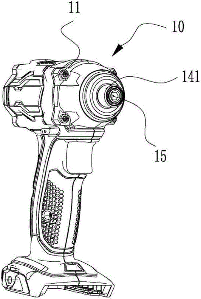
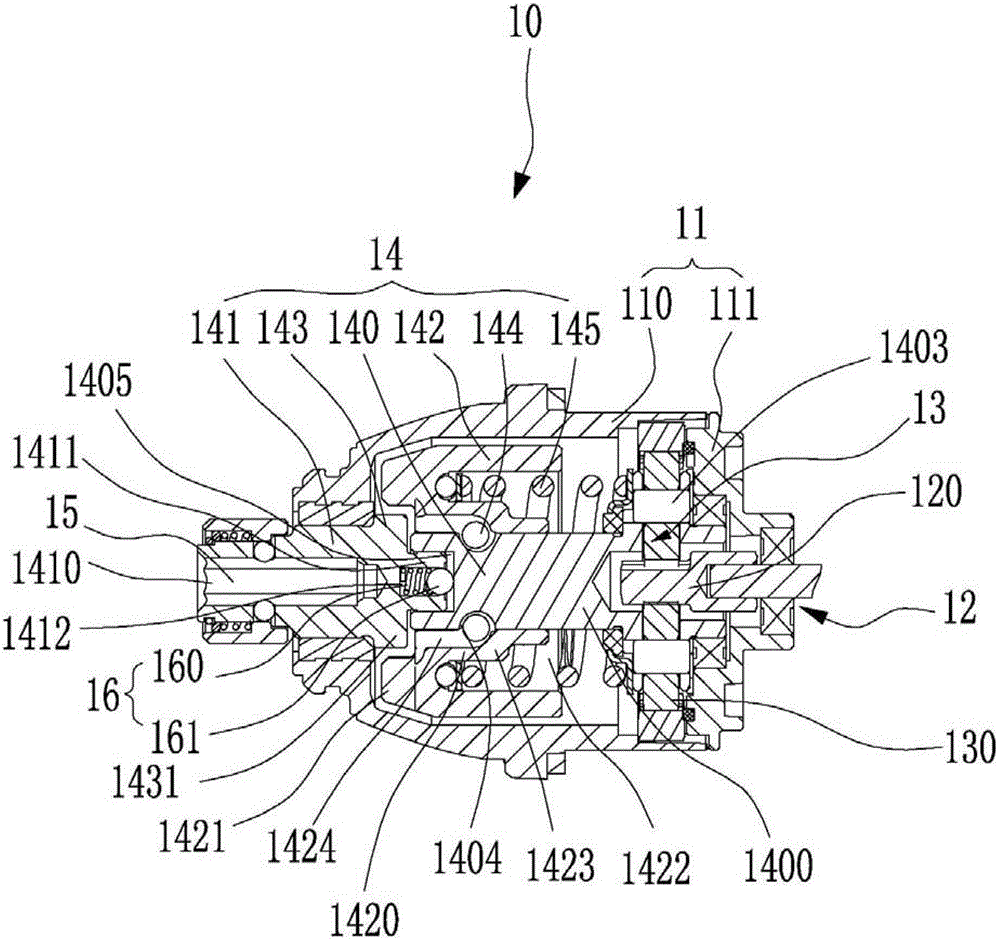
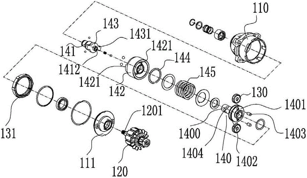
[0023] Please refer to figure 1 and figure 2 The electric tool 10 in the first embodiment of the present invention includes a housing 11, a power component 12, a speed reduction mechanism 13, an impact mechanism 14, an actuator 15 and a shock absorbing mechanism 16. In this embodiment, an impact screwdriver is used as an example The electric tool 10 will be described in detail.

[0024] The casing 11 includes a front casing 110 and a rear casing 111 , and the front casing 110 and the rear casing 111 are screwed together. It can be understood that the front case 110 and the rear case 111 can also be connected by clamping or other connection methods, as long as the connection method can connect the front case 110 and the rear case 111 as a whole and is easy to disassemble, it should belong...


PUM


Abstract

An electric power tool comprises a casing, a power component, a speed reducing mechanism, an impact mechanism, an actuating mechanism and a damping mechanism. The electric power tool provided by the invention is characterized in that the damping mechanism is arranged between a main shaft and an output shaft and located in a containing hole of the main shaft or the output shaft; the damping mechanism comprises a supporting element and an elastic element which is connected with the supporting element; the supporting element and the elastic element are extruded and assembled into a whole and the clearance between the supporting element and the elastic element is always zero through the automatic adjustment of the elastic element, so that the impact sound generated during the process of shaking the electric power tool is avoided and the friction between the damping mechanism and the main shaft or output shaft is reduced as a result of the point contact between the supporting component and the main shaft or the output shaft, thereby ensuring the rotational efficiency of the output shaft. The electric power tool provided by the invention has the advantages of simple and compact structure and low cost.

Description

technical field [0001] The invention relates to an electric tool, in particular to an impact electric tool. Background technique [0002] In impact electric tool products such as impact wrench, impact screwdriver, impact drill, etc., in order to prevent the output shaft from being stuck and affect the rotation efficiency, at the same time, due to the limitation of processing level, it is impossible to ensure the connection between the output shaft assembly and the gearbox housing and the main shaft. For tight fit, a certain serial movement gap is generally preset before and after the output shaft to ensure high-efficiency operation of the output shaft. Generally, consumers are accustomed to shaking power tools back and forth when purchasing, but due to the lack of tight fit, the output shaft will produce impact sounds when the output shaft moves back and forth in series, which makes consumers mistakenly think that the product has quality problems and give up buying. [0003...

Claims


Application Information

Patent Timeline
Patent Type & Authority Patents(China)
IPC IPC(8): B25D16/00B25D17/00F16F15/134
Inventor 王小勇赵祥
Owner NANJING CHERVON IND
Learn More