Compensated single-trailing-arm hydraulic driving hanging system for engineering vehicle

An engineering vehicle and active suspension technology, which is applied in the direction of vehicle components, suspensions, elastic suspensions, etc., can solve the problems that engineering vehicles cannot meet the obstacle-crossing ability and the space of the suspension system is limited, so as to improve the field passing ability and The effect of working ability, easy adjustment and large adjustment range

Inactive Publication Date: 2013-04-03
XUZHOU YANDA TRANSMISSION & CONTROL TECH
View PDF6 Cites 12 Cited by
  • Summary
  • Abstract
  • Description
  • Claims
  • Application Information

AI Technical Summary

Problems solved by technology

Since engineering vehicles usually have many functional systems, the space left for the suspension system is very limited, and the vehicle suspension needs to be adjusted with a large stroke to meet the complex road conditions. The existing suspension structures cannot meet these requirements.
Most of the suspension systems of existing engineering vehicles do not have or use the suspension system of the general motor chassis itself, and the suspension systems of the general motor chassis are mostly passive suspension systems composed of traditional shock absorbers and shock absorbing springs, which leads to Engineering vehicles corresponding to complex road conditions in the field cannot meet sufficient passability and high obstacle-surpassing ability, as well as road adaptability and working stability

Method used


Image

  • Compensated single-trailing-arm hydraulic driving hanging system for engineering vehicle
  • Compensated single-trailing-arm hydraulic driving hanging system for engineering vehicle
  • Compensated single-trailing-arm hydraulic driving hanging system for engineering vehicle

Examples


Embodiment

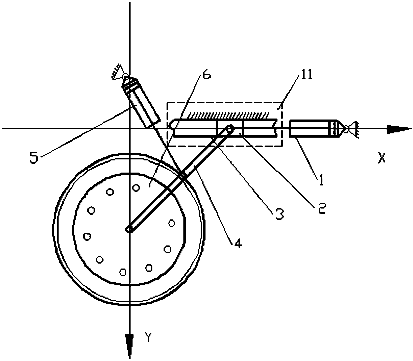
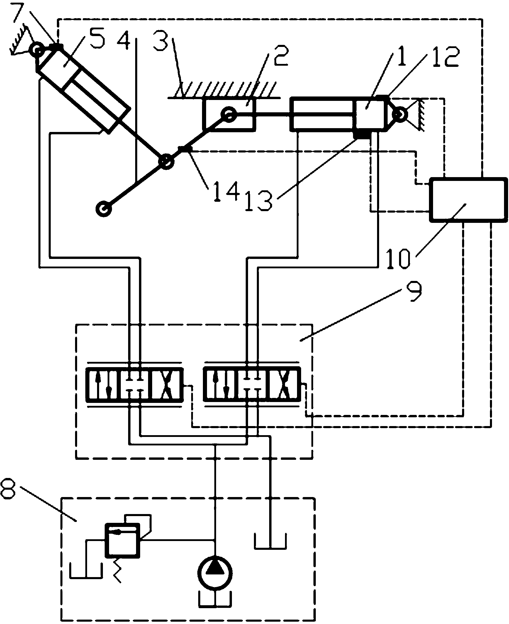
[0015] figure 1 , 2 It is an embodiment disclosed by the present invention. This engineering vehicle compensation type single trailing arm hydraulic active suspension system includes a compensation hydraulic cylinder 1 , a suspension hydraulic cylinder 5 , a hydraulic control valve 9 and a constant pressure hydraulic oil source 8 . One end of the suspension arm 4 of the compensated single trailing arm hydraulic active suspension system of engineering vehicles is connected to the wheel side drive system 6, and the other end is connected to the compensation slider 2 of the lateral displacement compensation mechanism 11, and the compensation slider 2 is connected to the compensation hydraulic cylinder 1 , the compensation hydraulic cylinder 1 is connected with a hinge fixed on the vehicle body. The middle part of the suspension arm 4 is connected with a suspension hydraulic cylinder 5, and the suspension hydraulic cylinder 5 is connected with a hinge fixed on the vehicle body. ...


PUM


Abstract

The invention discloses a compensated single-trailing-arm hydraulic driving hanging system for an engineering vehicle. One end of a hanging arm (4) of the hanging system is connected with a wheel edge driving system (6), the other end of the hanging arm (4) is connected with a compensation slide block (2) of a lateral displacement compensation mechanism (11), the compensation slide block (2) and a compensation hydraulic cylinder (1) are mutually connected, the compensation hydraulic cylinder (1) is connected with a whole body hinge, the middle part of the hanging arm (4) is connected with a hanging hydraulic cylinder (5), and the hanging hydraulic cylinder (5) is connected with the vehicle body hinge. The compensation hydraulic cylinder (1) and the hanging hydraulic cylinder (5) are connected with a hydraulic control valve block (9) through a pipeline, and the hydraulic control valve block (9) is connected with a constant-pressure hydraulic oil source (8) through a pipeline. Two hydraulic cylinders are used for driving one hanging arm, a controller is used for controlling the two hydraulic cylinders in real time according to the ground condition or the artificially input parameters, and a hanging wheel shaft moves according to specified requirements. The compensated single-trailing-arm hydraulic driving hanging system has the advantages that the occupied space is small, the regulation quantity of the gap from an underpan to the ground is great, and the like.

Description

technical field [0001] The invention relates to an engineering vehicle suspension system, in particular to an engineering vehicle compensation type single trailing arm hydraulic active suspension system adapted to field complex terrain operations. Background technique [0002] In order to obtain good passability under complex road conditions in the field, the suspension system of engineering vehicles is an important part to improve passability and vehicle stability. Since engineering vehicles usually have many functional systems, the space left for the suspension system is very limited, and the vehicle suspension needs to be adjusted with a large stroke to meet the complex road conditions. The existing suspension structures cannot meet these requirements. Most of the suspension systems of existing engineering vehicles do not have or use the suspension system of the general motor chassis itself, and the suspension systems of the general motor chassis are mostly passive suspen...

Claims


Application Information

Patent Timeline
Patent Type & Authority Applications(China)
IPC IPC(8): B60G17/00B60G17/08
Inventor 高英杰宁博宋渭滨高雪涛
Owner XUZHOU YANDA TRANSMISSION & CONTROL TECH
Why Eureka
Try Eureka