Braking control unit for high-speed motor train units and urban rail transit vehicles

A high-speed EMU and brake control technology, applied in pneumatic brakes, hydrodynamic brakes, hydrostatic brakes, etc., can solve problems such as inconvenient maintenance, and achieve the effects of convenient maintenance, easy use and high interchangeability

Active Publication Date: 2013-04-03
CRRC QINGDAO SIFANG ROLLING STOCK RES INST +1
5 Cites 10 Cited by

AI-Extracted Technical Summary

Problems solved by technology

[0005] The present invention aims at the above-mentioned deficiencies of the existing control unit in the braking process, such as inaccurate and stable control of the braking force and inconvenient maintenance, and provides a control unit that can meet the emergency braking action control requirements of the microcomputer-controlled...

Method used

Above-mentioned emergency valve 2 is provided with solenoid valve, and solenoid valve can work reliably under long-term charged state, and response time is short.
In order to realize that the air pressure from the brake air storage cylinder is converted into a pre-control pressure corresponding to the el...

Abstract

The invention relates to a braking control unit for high-speed motor train units and urban rail transit vehicles. The braking control unit comprises an empty electric converting valve, an emergency valve, an empty and load vehicle valve and a relay valve, wherein the empty electric converting valve is connected with the emergency valve through a pipeline, the emergency valve is connected with the empty and load vehicle valve through a pipeline, the empty and load vehicle valve is connected with the relay valve through a pipeline, the braking control unit also comprises a connecting plate and an integrated air path plate arranged on the connecting plate, the connecting plate is arranged on a hanging frame arranged at the bottom of a vehicle body, the empty electric converting valve, the emergency valve, and the empty and load vehicle valve and the relay valve are respectively arranged on the integrated air path plate. The braking control unit has the advantages that the modularized design is adopted, the empty electric converting valve, the emergency valve, the empty and load vehicle valve and the relay valve are integrated on the integrated air path plate, the braking control unit is arranged on a hanging frame arranged at the bottom of a vehicle body in an integral hoisting mode, higher interchangeability is realized, and the maintenance is convenient.

Application Domain

Railway hydrostatic brakesRailway hydrodynamic brakes +1

Technology Topic

Image

  • Braking control unit for high-speed motor train units and urban rail transit vehicles
  • Braking control unit for high-speed motor train units and urban rail transit vehicles
  • Braking control unit for high-speed motor train units and urban rail transit vehicles

Examples

  • Experimental program(1)

Example Embodiment

[0024] The present invention will be further described in detail below in conjunction with the drawings.
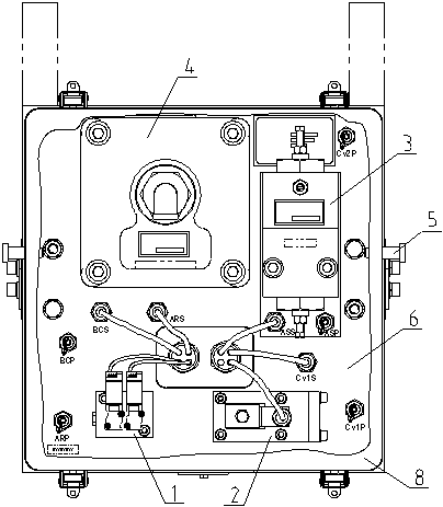
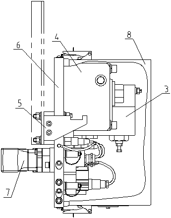
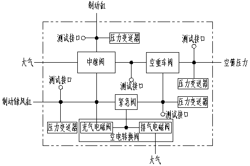
[0025] Such as figure 1 As shown, a brake control unit for high-speed EMUs and urban rail transit vehicles includes an air-to-electric conversion valve 1, an emergency valve 2, an empty-to-load valve 3, and a relay valve 4, wherein the air-to-electric conversion valve 1 passes through a pipe The emergency valve 2 is connected to the emergency valve 2, the emergency valve 2 is connected to the empty and heavy vehicle valve 3 through the pipeline, and the empty and heavy vehicle valve 3 is connected to the relay valve 4 through the pipeline. The brake control unit also includes a connecting plate 5 and is installed on the connecting plate 5. The integrated gas circuit board 6 is installed, and the connecting plate 5 is installed on the hanger at the bottom of the car body; the air-to-electric conversion valve 1, the emergency valve 2, the empty and heavy car valve 3 and the relay valve 4 are all installed on the integrated gas circuit board 6.
[0026] When the vehicle is at a standstill, in order to enable external equipment to test the air spring pressure, brake cylinder pressure, pre-control pressure and air storage cylinder pressure, the integrated air circuit board 6 is also provided with an air spring pressure test interface and brake Cylinder pressure test interface, pre-control pressure test interface and air storage cylinder pressure test interface are used to test the air spring pressure, brake cylinder pressure, pre-control pressure and air storage cylinder pressure respectively.
[0027] The air spring pressure test interface, brake cylinder pressure test interface, pre-control pressure test interface and air storage cylinder pressure test interface are all equipped with pressure sensors on the interface pipes to detect the air spring pressure, brake cylinder pressure, and pre-control Pressure and air accumulator pressure.
[0028] The air spring pressure test interface, brake cylinder pressure test interface, pre-control pressure test interface and air storage cylinder pressure test interface are all interfaces that adopt the quick plug-in method.
[0029] In order to realize the communication between the brake control unit and the electronic control unit, an electrical connector 7 that can be quickly disconnected is installed on the back of the integrated gas circuit board 6, and the brake control unit is connected to the electronic control unit through the electrical connector 7 connection.
[0030] In order to realize the conversion of the air pressure from the brake air reservoir into the pre-control pressure corresponding to the electrical signal of the electronic control unit, the air-to-electric conversion valve 1 is provided with a charging solenoid valve 9 and an exhaust solenoid valve 10, and the solenoid valve adopts The high-frequency switching solenoid valve can ensure the fine adjustment of the air pressure.
[0031] The emergency valve 2 is provided with a solenoid valve, which can work reliably in a long-term energized state and has a short response time.
[0032] The empty and heavy vehicle valve 3 adopts the lever balance type, which can continuously adjust the pre-control pressure according to the change of the vehicle load, and the ratio and the adjustment range of the pre-control pressure and the air spring pressure can be adjusted; the relay valve 4 can be adjusted according to the pre-control pressure Change, fine, fast and proportional adjustment of brake pressure.
[0033] In order to make the brake control unit waterproof and dustproof, the brake control unit is also provided with a protective cover 8 which is installed on the integrated air circuit board 6.
[0034] Under normal braking conditions, the air-to-electric switch valve generates a pre-control pressure that is compatible with the braking force demand according to the control signal of the electronic control unit. The pre-control pressure is adapted to the vehicle load. The generation process is limited by the anti-impulse requirements. The control pressure passes through the emergency valve and the empty and heavy vehicle valve to the relay valve and becomes the pilot control pressure of the relay valve. The relay valve opens the passage between the brake air reservoir and the brake cylinder to meet the requirements of normal braking. The brake cylinder pressure.
[0035] In the case of emergency braking, the compressed air of the brake air cylinder passes through the emergency valve to the brake empty and heavy vehicle valve. The empty and heavy vehicle valve is adjusted according to the vehicle load to form a pre-control pressure and reach the relay valve to become the relay valve. The pilot control pressure makes the relay valve open the passage between the brake air storage cylinder and the brake cylinder to form a brake cylinder pressure that meets the requirements of emergency braking.
[0036] Working principle: During normal braking, the brake control unit converts the air pressure from the brake air reservoir into the pre-control pressure corresponding to the electrical signal through the charging and exhaust solenoid valves according to the electrical signal from the electronic control unit , And then the pre-control pressure reaches the empty and heavy vehicle valve via the emergency valve (the emergency solenoid valve is energized at this time, connecting the path between the air-to-electricity switching valve and the empty and heavy vehicle valve), and is detected and restricted by the empty and heavy vehicle valve. The pre-control pressure from the empty and heavy vehicle valve is sent to the relay valve to open the passage between the brake air reservoir and the brake cylinder in the relay valve, and finally the brake cylinder obtains the air pressure that meets the braking force requirements.
[0037] During emergency braking, the emergency valve is de-energized, and the passage between the brake air reservoir and the empty and heavy vehicle valve is connected. The compressed air from the brake air reservoir directly reaches the empty and heavy vehicle adjustment valve through the emergency valve to pre-control the pressure. Only controlled by the empty and heavy vehicle valve, from the pre-control pressure from the empty and heavy vehicle valve to the relay valve, open the passage between the brake air reservoir and the brake cylinder in the relay valve, and finally make the brake cylinder obtain emergency braking pressure . If the emergency valve fails and the path between the brake air reservoir and the empty and load valve is not connected, the electronic control unit will generate the pre-control pressure through the air-to-electric switch valve according to the set emergency braking force to implement emergency braking. move.
[0038] When the electronic control unit issues a release command, the exhaust solenoid valve in the brake control unit is energized and opened, the charging solenoid valve is blocked, the pre-control pressure is exhausted to the atmosphere through the exhaust valve, and the brake control unit relay valve diaphragm moves to cut off the storage. The passage between the air cylinder and the brake cylinder opens the passage between the brake cylinder and the atmosphere, and the brake cylinder exhausts the atmosphere.
[0039] During the braking and relief process, the pressure of the brake air cylinder, the pre-control pressure, the pressure of the brake cylinder and the air spring pressure are detected by the pressure sensors, and the corresponding pressure can be tested through the pressure test interfaces.
[0040] During normal braking, the emergency valve can be used as a backup control component of the charging solenoid valve.
[0041] During emergency braking, the charging and exhaust solenoid valves can generate backup emergency pressure.

PUM

no PUM

Description & Claims & Application Information

We can also present the details of the Description, Claims and Application information to help users get a comprehensive understanding of the technical details of the patent, such as background art, summary of invention, brief description of drawings, description of embodiments, and other original content. On the other hand, users can also determine the specific scope of protection of the technology through the list of claims; as well as understand the changes in the life cycle of the technology with the presentation of the patent timeline. Login to view more.

Similar technology patents

Optical record control system

InactiveCN1737913AImprove hardware efficiencyImprove interchangeabilityInformation arrangementOptical record carriersChannel dataData error
Owner:LEJIN GUANGDIAN ELECTRONIC CO LTD SHANGHAI

Classification and recommendation of technical efficacy words

  • Improve interchangeability
  • Easy to maintain
Why Eureka
Try Eureka