Thread creation element for a spinning position of an air jet spinning machine and method for preparing a spin process on an air jet spinning machine

A technology of air-jet spinning machine and components, which is applied in the direction of spinning machine, continuous winding spinning machine, textile and paper making, and can solve the problem that the error situation cannot be completely eliminated

Inactive Publication Date: 2013-04-03
MASCHINENFABRIK RIETER AG
View PDF1 Cites 3 Cited by
  • Summary
  • Abstract
  • Description
  • Claims
  • Application Information

AI Technical Summary

Problems solved by technology

In most cases, the feeding back of the yarn end in the area between the supply roller and the fiber guide element can be achieved without problems by means of the air flow, but error cases cannot be completely ruled out

Method used


Image

  • Thread creation element for a spinning position of an air jet spinning machine and method for preparing a spin process on an air jet spinning machine
  • Thread creation element for a spinning position of an air jet spinning machine and method for preparing a spin process on an air jet spinning machine
  • Thread creation element for a spinning position of an air jet spinning machine and method for preparing a spin process on an air jet spinning machine

Examples


Embodiment Construction

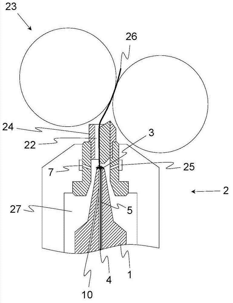
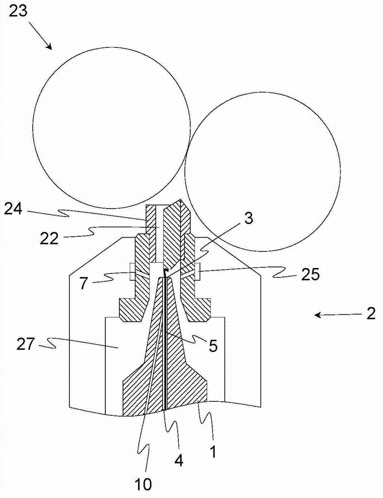
[0032] figure 1 The spinning position 2 of an air-jet spinning machine according to the prior art is shown in a partially cutaway side view. The spinning position 2 contains a fiber guide element 24 through which the fiber material 26 to be spun and which is mostly present as a drawn fiber strip reaches the so-called swirl chamber 27 of the spinning position 2, in which Finally, the original spinning process is carried out. The drafting usually takes over a drafting unit arranged upstream of the fiber guide element 24 , from which the drafted fiber strip is drawn by means of a pair of withdrawal rollers. Finally, the fiber strip is preferably gripped by the pair of rollers serving as the pair of supply rollers 23 which should be arranged as directly as possible in connection with the fiber guide element 24 in order to avoid false delays.

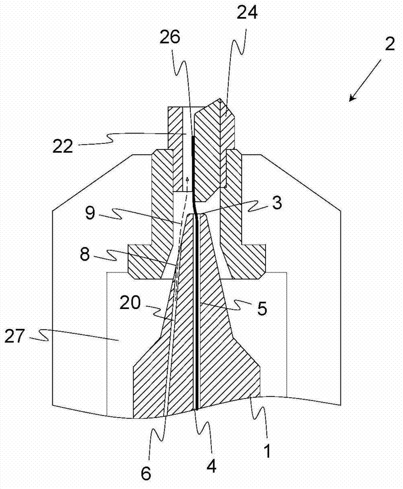
[0033] After the fiber material 26 has passed the fiber guide element 24 via the guide channel 22 , it reaches the area of ​​a plurality ...


PUM


Abstract

The element (1) has an inlet opening (3) formed at a front end of the element, and a discharging duct (4) for discharging yarn and extending from a region of the inlet opening within the element. An injection channel (6) partially runs within a wall that surrounds the discharging duct. The injection channel opens into an outlet opening (8) that is formed in a region of an outer surface of the element. An air duct runs within the wall and opens into the discharging duct at an acute angle. The injection channel and the air duct open into a common air supply channel and formed as a hole. The element is provided with a lid element that is made of plastic. An independent claim is also included for a method for performing a spinning process at a spinning area of an air jet spinning machine.

Description

technical field [0001] The invention relates to a thread forming element for the spinning position of an air-jet spinning machine, wherein the thread forming element has an inlet hole on the end side and a discharge channel for the yarn, the discharge channel being located in the inlet hole Originating in the region of and extending inside the yarn forming element. Furthermore, a method for preparing the piecing process (Anspinnvorgnag) on ​​the spinning position of an air-jet spinning machine is described, wherein the spinning position contains a yarn forming element and fibers arranged in the spinning direction before the yarn forming element A guide element, the yarn forming element has a discharge channel for the yarn produced inside the spinning position, the fiber guide element has a guide channel for the fiber strip transported to the spinning position. Background technique [0002] After a yarn break occurs on an air-jet spinning machine, it is common practice that ...

Claims


Application Information

Patent Timeline
Patent Type & Authority Applications(China)
IPC IPC(8): D01H1/115
CPCD01H1/115
Inventor 彼得·阿茨特K·齐格勒海因茨·穆勒乌韦·海特曼M·库布勒
Owner MASCHINENFABRIK RIETER AG
Why Eureka
Try Eureka