Valve for preventing hydraulic motor from reversing
A hydraulic motor and reversing valve technology, applied in the direction of servo motor components, fluid pressure actuators, mechanical equipment, etc., can solve the problem of not better eliminating and absorbing the pressure shock of the working oil port of the hydraulic motor, and reducing the rotary manipulation of construction machinery Performance, overflow valve is difficult to superimpose and other problems, to achieve the effect of light weight, smooth stop, and reverse rotation prevention
- Summary
- Abstract
- Description
- Claims
- Application Information
AI Technical Summary
Problems solved by technology
Method used
Image

Examples
Embodiment Construction
[0023] Embodiments of the present invention will be further described in detail below in conjunction with the accompanying drawings.
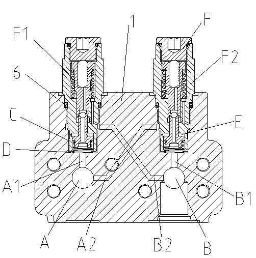
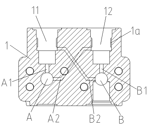
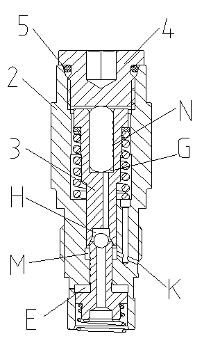
[0024] Figure 1 to Figure 7 Shown is the structural representation of the present invention.
[0025] The reference signs are: the first working oil port A, the first connecting oil passage A1, the first pressure relief passage A2, the second working oil port B, the second connecting oil passage B1, the second pressure relief passage B2, the ring Oil passage C, clearance oil passage D, lower buffer chamber E, unit buffer valve F, first unit buffer valve F1, second unit buffer valve F2, hydraulic chamber G, check valve chamber H, oil drain port K, oil drain Chamber M, annular oil storage tank N, transition block 1, internal thread 1a, first installation cavity 11, second installation cavity 12, valve body 2, valve external thread 2a, upper valve cavity 21, annular limit plane 211, valve Rod chamber 22, annular groove 221, oil drain passage 22...
PUM
 Abstract
Description
Claims
Application Information