Hydraulic oil supply unit, hydraulic power unit and oil supply control method of hydraulic oil supply unit

An oil supply unit and oil supply control technology, which is applied in fluid pressure actuation devices, fluid pressure actuation system components, mechanical equipment, etc., can solve the problems of inability to maintain precision constant pressure oil supply, reduced pressure regulation accuracy, and overflow loss major issues

Active Publication Date: 2013-04-03
ZOOMLION HEAVY IND CO LTD
View PDF11 Cites 9 Cited by
  • Summary
  • Abstract
  • Description
  • Claims
  • Application Information

AI Technical Summary

Problems solved by technology

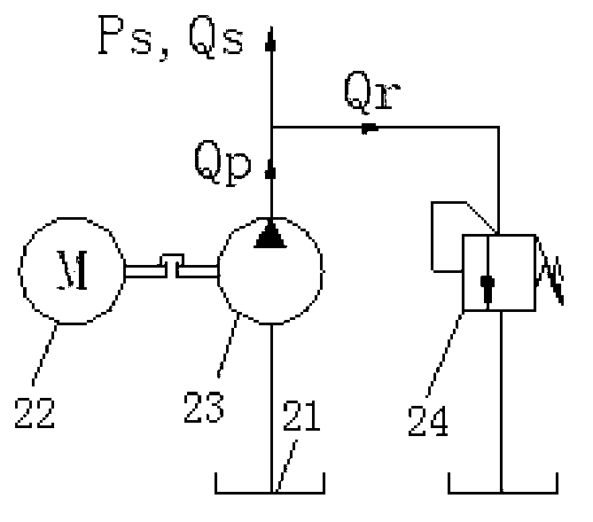
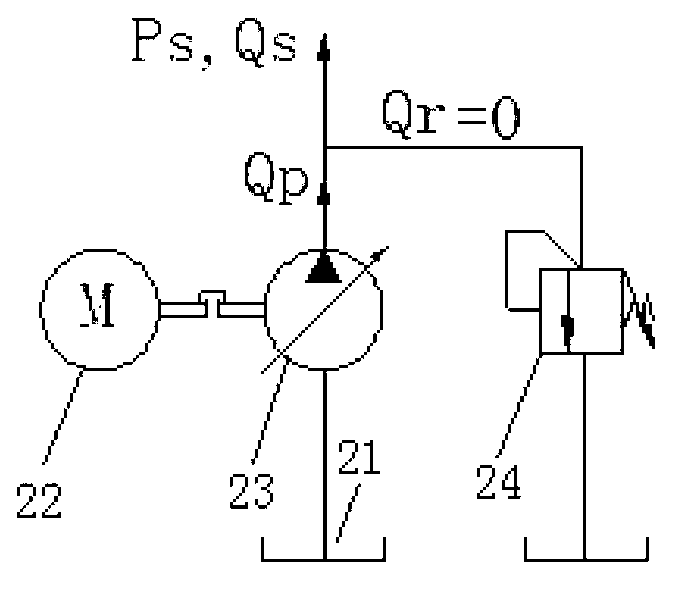
[0007] First, the pressure regulation accuracy of the relief valve is reduced. Under the same setting pressure of the pressure regulating spring, the adjustment pressure of the relief valve with a small overflow flow is smaller than that of the relief valve with a large overflow flow. Pressure, that is, the relief valve has a large pressure regulation deviation due to the change of the relief flow
[0008] Second, the throttling loss of the relief valve changes, and the throttling loss is proportional to the overflow flow. When the hydraulic pump station operates under the condition of large overflow flow, the overflow loss of the constant pressure hydraulic pump station is very large. The efficiency is very low, and most of the hydraulic oil pumped by the hydraulic pump flows back to the oil tank through the overflow valve, wasting energy
However, the overflow flow of the existing constant-pressure hydraulic pump station has a large range of changes, which will reduce the pressure regulation accuracy, resulting in unstable system pressure Ps, and cannot maintain a sufficiently sta

Method used


Image

  • Hydraulic oil supply unit, hydraulic power unit and oil supply control method of hydraulic oil supply unit
  • Hydraulic oil supply unit, hydraulic power unit and oil supply control method of hydraulic oil supply unit
  • Hydraulic oil supply unit, hydraulic power unit and oil supply control method of hydraulic oil supply unit

Examples


Embodiment Construction

[0078] The specific embodiments of the present invention will be described in detail below in conjunction with the accompanying drawings. It should be understood that the specific embodiments described here are only used to illustrate and explain the present invention, and the protection scope of the present invention is not limited to the following specific embodiments. .

[0079] It is stated in advance that the hydraulic oil supply unit of the present invention is not only suitable for the above-mentioned hydraulic pump station, but also can be used as a hydraulic oil supply system for mobile engineering machinery, and the specific application field does not constitute a limit to the protection scope of the present invention . The hydraulic components used in the hydraulic oil supply unit of the present invention basically belong to the commonly used hydraulic components in the hydraulic field. For those skilled in the hydraulic field, most hydraulic technology innovations ...


PUM


Abstract

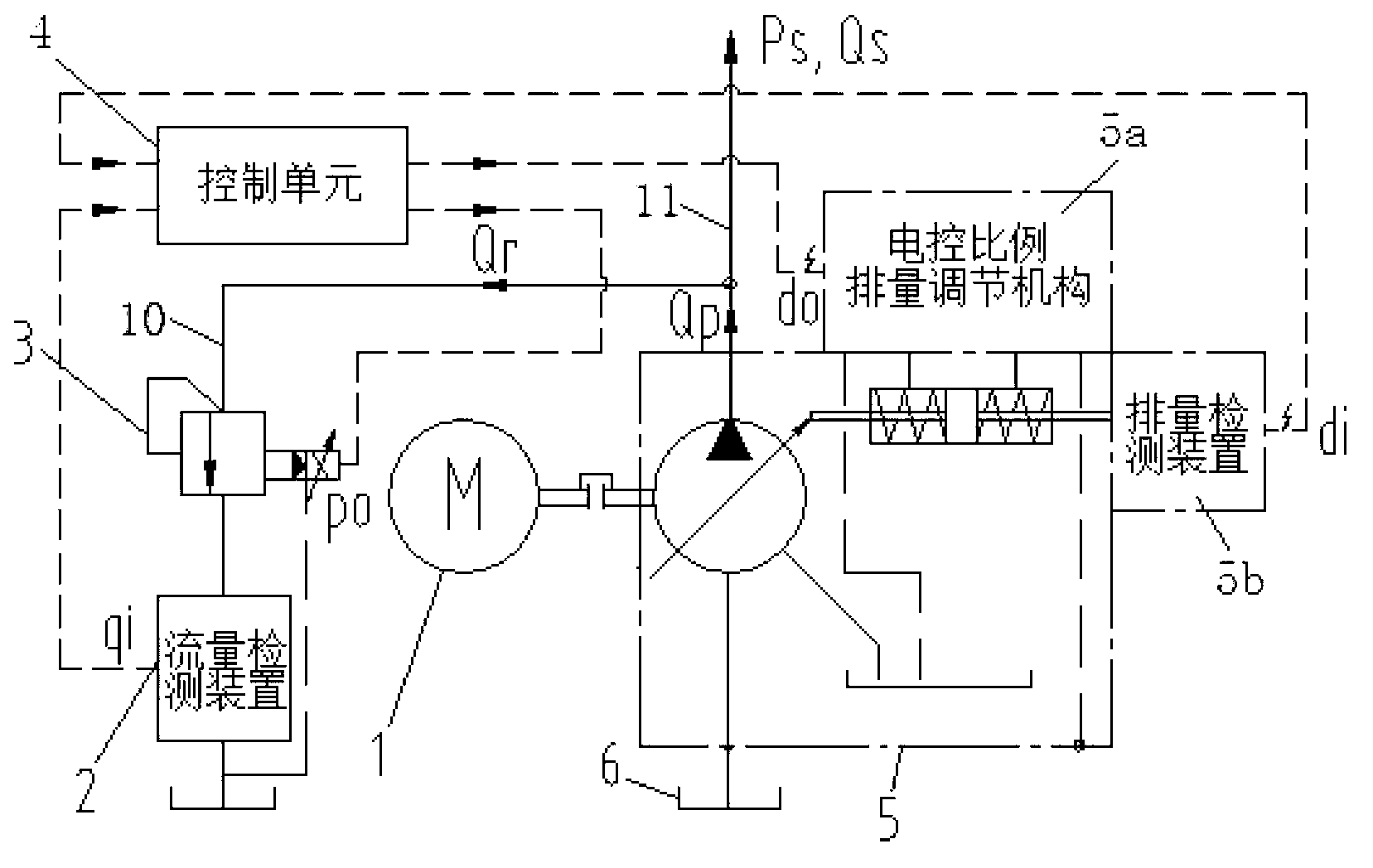
The invention relates to a hydraulic oil supply unit which comprises an oil flow regulating device, an oil pressure regulating device, a control unit (4) and an oil supply control oil way (10), wherein the oil supply control oil way (10) is provided with a flow detection device (2); one of the oil flow regulating device and the oil pressure regulating device is arranged on the oil supply control oil way (10), and the other one is used for controlling a hydraulic pump; the oil flow regulating device and the oil pressure regulating device are respectively and electrically connected with the control unit (4), so as to regulate the oil flow (Qs) and the oil pressure (Ps) of the hydraulic oil supply unit through the control of the control unit; and the flow detection device (2) is electrically connected with the control unit. In addition, the invention further provides an oil supply control method and a hydraulic power unit of the hydraulic oil supply unit. In the aspects of constant pressure oil supply control, constant-current source oil supply control and the like, the hydraulic oil supply unit, the hydraulic power unit and the oil supply control method have the advantages of higher control flexibility, wider applicability and better energy saving, and the control precision is obviously increased.

Description

technical field [0001] The invention relates to a hydraulic oil supply unit for supplying hydraulic oil to a hydraulic system. Further, the present invention relates to a hydraulic pump station comprising the hydraulic oil supply unit. In addition, the present invention also relates to an oil supply control method using the hydraulic oil supply unit. Background technique [0002] The hydraulic pump station is mainly used to supply hydraulic oil to the hydraulic system of mechanical equipment, which generally includes motors, hydraulic pumps, oil tanks, etc. According to application requirements, the hydraulic pump station can be a constant pressure hydraulic pump station or a constant flow hydraulic pump station. In the prior art, the constant pressure hydraulic pump station generally adopts the form of quantitative pump plus relief valve, which can provide hydraulic oil with constant pressure to the load. Part of the hydraulic oil flow output by the quantitative pump is s...

Claims


Application Information

Patent Timeline
IPC IPC(8): F15B21/08
Inventor 张军花袁野邹婿邵刘之安张劲
Owner ZOOMLION HEAVY IND CO LTD
Why Eureka
Try Eureka