LED shadowless lamp system with failure detection and repair functions

A LED shadowless lamp and faulty technology, applied in the field of lighting, can solve the problems of affecting the quality of surgery, difficulty in ensuring the accuracy of light brightness, unfavorable doctors' surgical treatment, etc., and achieve the effect of avoiding affecting lighting

Inactive Publication Date: 2013-04-03
杨夏芳
View PDF4 Cites 21 Cited by
  • Summary
  • Abstract
  • Description
  • Claims
  • Application Information

AI Technical Summary

Problems solved by technology

[0004] On the other hand, the LED in the LED shadowless lamp is driven by a constant current source. In the working area, its illuminance value is approximately proportional to the driving current. The purpose of dimming can be achieved by configuring the controller to adjust the driving current, but this dimming is The operator manually adjusts according to his own comfort, and the accuracy of the brightness is difficult to guarantee
[0005] During the operation, the doctor's body, head, hands and instruments will block the operation site and form a shadow. If it is not eliminated in time, it will affect the quality of the operation
Therefore, the biggest danger during the operation is that the LED shadowless lamp fails, which affects the lighting, which is not conducive to the doctor's surgical treatment activities.
In the actual operation process, there is often the danger of such a LED shadowless lamp malfunctioning.

Method used


Image

  • LED shadowless lamp system with failure detection and repair functions
  • LED shadowless lamp system with failure detection and repair functions
  • LED shadowless lamp system with failure detection and repair functions

Examples


Embodiment Construction

[0020] In order to make the content of the present invention clearer and easier to understand, the content of the present invention will be described in detail below in conjunction with specific embodiments and accompanying drawings.

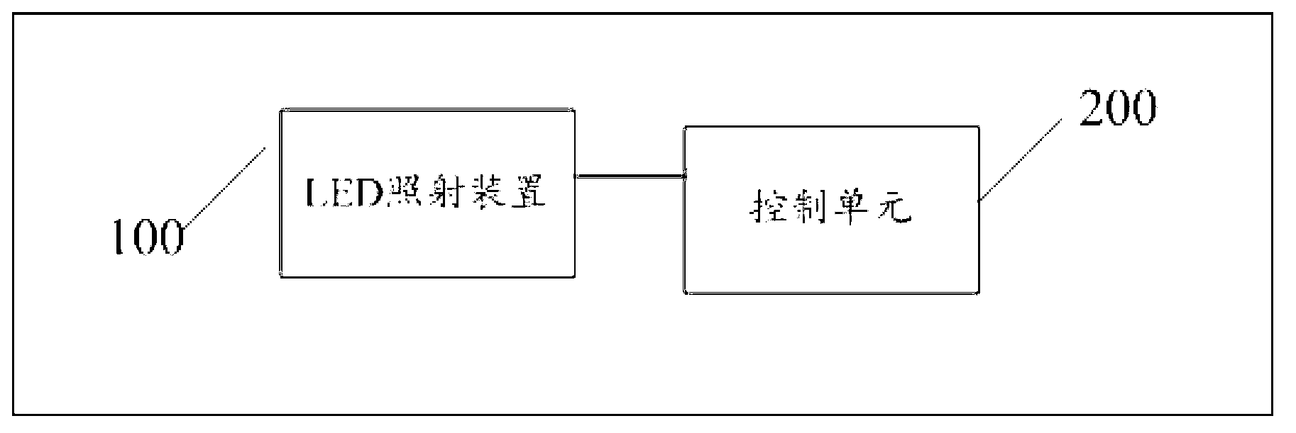
[0021] figure 1 A system block diagram of an LED shadowless lamp system according to an embodiment of the present invention is schematically shown.

[0022] like figure 1 As shown, the LED shadowless lamp system according to the embodiment of the present invention includes: an LED illuminating device 100 and a control unit 200 .

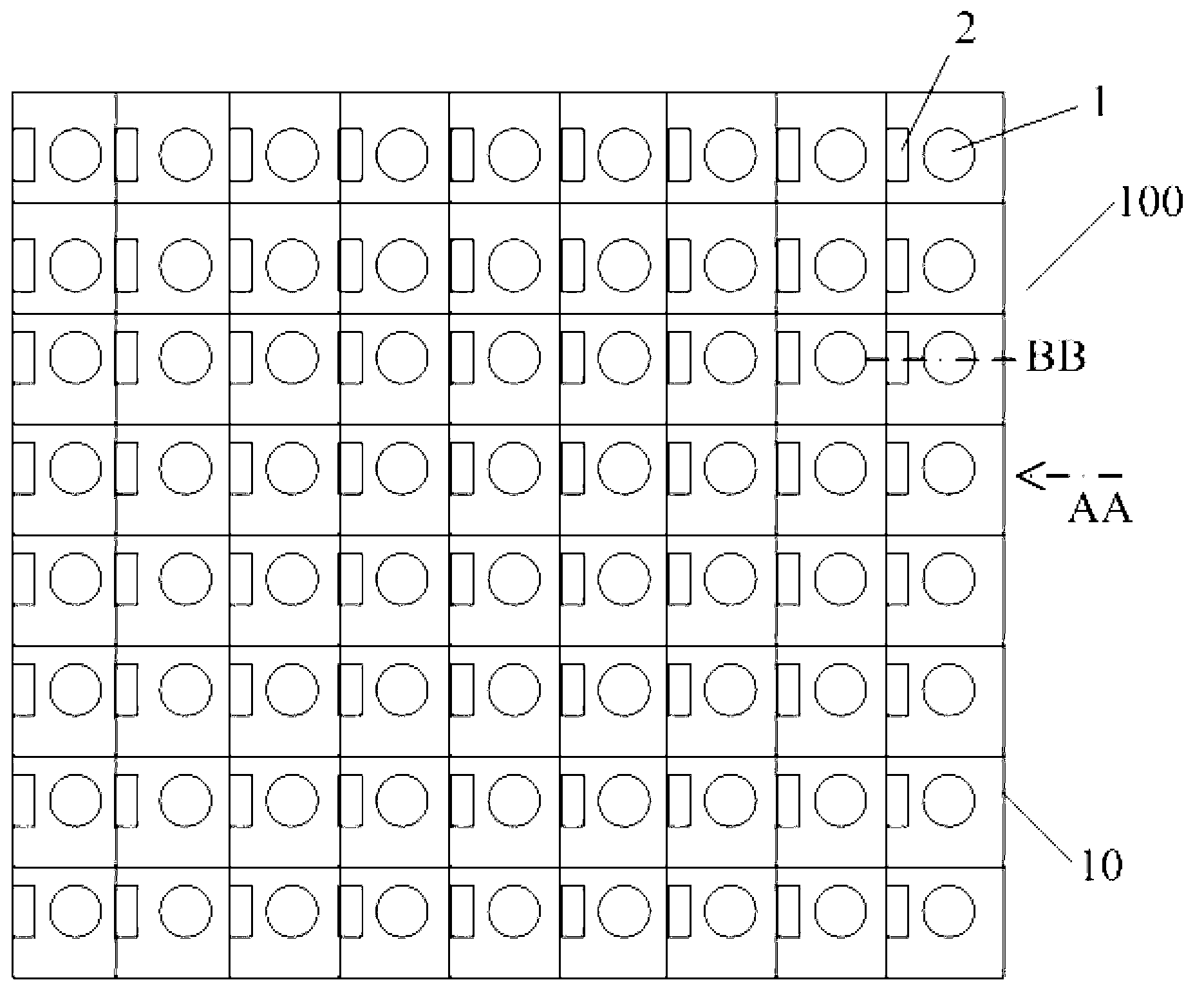
[0023] figure 2 A schematic diagram of an LED illuminating device of an LED shadowless lamp system according to an embodiment of the present invention is schematically shown.

[0024] like figure 2 As shown, the LED lighting device 100 according to the embodiment of the present invention includes: an LED arrangement frame 10, wherein the LED arrangement frame 10 includes a plurality of accommodation units, for ex...


PUM


Abstract

The invention provides an LED shadowless lamp system with failure detection and repair functions, which comprises an LED irradiation device and a control unit, wherein the LED irradiation device comprises an LED layout frame body, LED light-emitting elements and light sensing units; the control unit is used for providing light that is used for sending drive control signals to the LED light-emitting elements and standby LED elements thereof so as to control the LED light-emitting elements; the LED layout frame body is divided into a plurality of accommodating units, wherein the LED light-emitting element or the standby LED element thereof are arranged at the bottom of each accommodating unit, and the light sensing unit is arranged on the side wall of each accommodating unit; when LED array display equipment is started, the light sensing units sense the light given out by the LED light-emitting elements, and luminous signals corresponding to the LED light-emitting elements are transmitted to the control unit by the light sensing units; and when the control unit judges that the LED light-emitting elements work abnormally, the standby LED elements of the LED light-emitting elements are started.

Description

technical field [0001] The present invention relates to the lighting field, and more specifically, the present invention relates to an LED shadowless lamp system equipped with fault detection and repair functions. Background technique [0002] Shadowless lamps are used for lighting surgery, for example. Surgical shadowless lamps are generally designed to eliminate shadows as much as possible and minimize color distortion. [0003] The principle of the shadowless lamp is to lighten the umbra so that the umbra is not obvious. The shadow is formed by light shining on the object. The middle part of the shadow is particularly dark, and the surrounding area is slightly lighter. The particularly dark part in the middle of the shadow is called the umbra, and the dark part around it is called the penumbra. These phenomena are closely related to the linear propagation of light. Generally, light can be irradiated onto the operating table from different angles, which not only ensures...

Claims


Application Information

Patent Timeline
Patent Type & Authority Applications(China)
IPC IPC(8): F21S8/00F21V23/04H05B37/03F21W131/20F21Y101/02F21Y115/10
Inventor 杨夏芳
Owner 杨夏芳
Why Eureka
Try Eureka