Solar evacuating and anti-freezing device
An anti-freezing device and solar energy technology, which is applied to solar thermal devices, solar thermal power generation, heating devices, etc., can solve the problems of freezing blocking of water storage, moving down pipelines, and freezing formation in pipes, etc., and achieves simple and durable structure, few moving parts, Easy lifting effect
- Summary
- Abstract
- Description
- Claims
- Application Information
AI Technical Summary
Problems solved by technology
Method used
Image
Examples
Embodiment 1
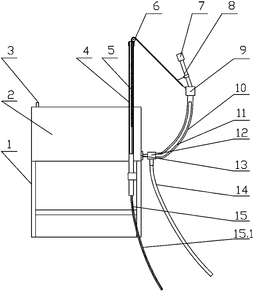
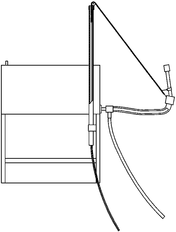
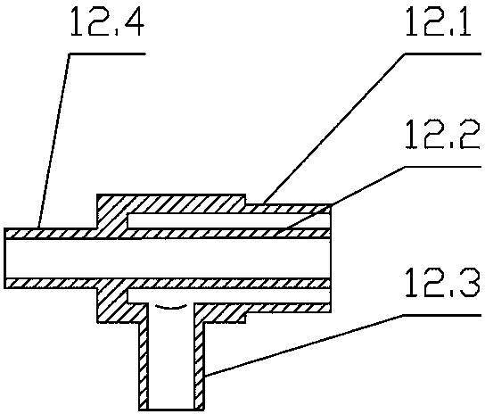
[0025] Such as figure 1 , figure 2 , image 3 As shown, a solar energy emptying and antifreezing device includes a lifting mechanism and an emptying hose assembly. The main body of the lifting mechanism is a bracket riser 4, and the bracket riser 4 is vertically fixed on the bracket 1 or the water tank of the solar water heater. , the upper end of the bracket riser 4 is higher than the water tank 2, and the upper end of the bracket riser 4 of the lifting mechanism is fixedly connected with a pulley 6, and the zipper 5 passes through the bracket riser and passes through the pulley 6 and the two parts of the emptying hose assembly. Connected through 9, the end of the zipper 5 is connected with the steel wire rope 15, and the outside of the steel wire rope is designed with a casing 15.1, and the lower end of the steel wire rope 15 is pulled manually or mechanically; the emptying hose assembly includes a special-shaped tee 12, a lifting hose, and a two-way 9 and air supply pipe...
Embodiment 2
[0027] Such as image 3 , Figure 4 As shown, a solar energy emptying and antifreezing device includes a lifting mechanism and an emptying hose assembly. The main body of the lifting mechanism is a bracket riser 4, and the bracket riser 4 is vertically fixed to the bracket 1 or the water tank 2 of the solar water heater. Above, the upper end of the standpipe 4 is higher than the water tank 2, a motor compartment 16 is fixed on the top of the support standpipe 4, a motor 17 is installed in the motor compartment 16, and one end of the lift pole 19 is fixed on the output shaft of the motor, and the lift pole 19 is fixed on the motor output shaft. 19 The other end passes through the arc groove on the motor compartment and connects with the joint 9 in the emptying hose assembly through the pull rope 21; the upper and lower parts of the arc groove are respectively designed with an upper limit switch 18 and a lower limit switch. Position switch 20; motor wire 22 passes through the b...
PUM
 Abstract
Description
Claims
Application Information
 - R&D
- Intellectual Property
- Life Sciences
- Materials
- Tech Scout
- Unparalleled Data Quality
- Higher Quality Content
- 60% Fewer Hallucinations
Browse by: Latest US Patents, China's latest patents, Technical Efficacy Thesaurus, Application Domain, Technology Topic, Popular Technical Reports.
© 2025 PatSnap. All rights reserved.Legal|Privacy policy|Modern Slavery Act Transparency Statement|Sitemap|About US| Contact US: help@patsnap.com


