Compressor

A technology for compressors and compressor housings, applied in the field of compressors, can solve problems such as low heat conduction efficiency, achieve gas-liquid separation, achieve stability, and improve work efficiency and practicability

Active Publication Date: 2013-04-03
BEIJING FULLLINK OREITH TECH CO LTD
View PDF4 Cites 2 Cited by
  • Summary
  • Abstract
  • Description
  • Claims
  • Application Information

AI Technical Summary

Problems solved by technology

[0004] The purpose of the present invention is to overcome the shortcomings of the prior art, and to solve the problem of pure liquid circulation and low heat conduction efficiency in the heat pipe heat exchange system, and to provide a compressor that passes through the two-phase flow next to the compressor body The design of the liquid storage stabilizer not only realizes the gas-liquid separation of the working medium, but also can reasonably distribute the flow ratio of the liquid working medium and the gas working medium in the circulation loop to form a stable two-phase flow of the working medium in the circulation loop

Method used


Image

  • Compressor
  • Compressor

Examples


Embodiment 1

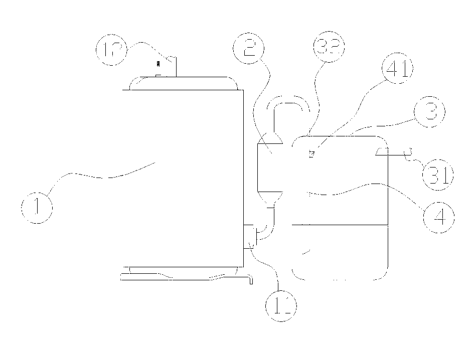
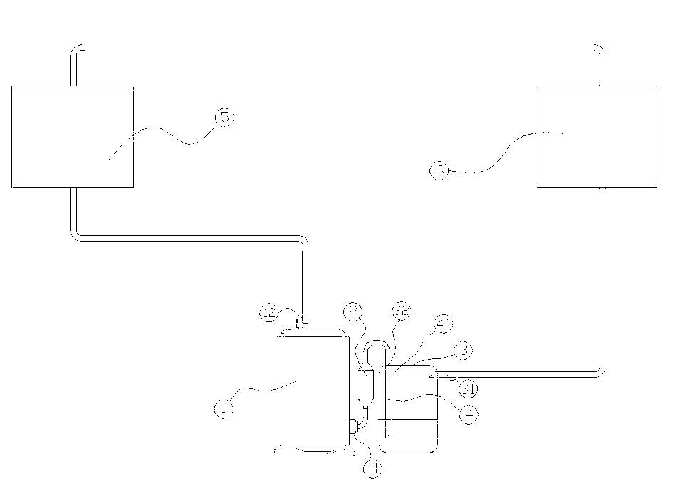
[0018] like figure 2 The schematic diagram of the compressor is shown, including the compressor body (1), the filter (2), the liquid storage tank (3) installed on the side of the compressor body through the bracket, and the gas-liquid secondary tank located in the liquid storage tank. Matching flow pipe (4), evaporator (5), condenser (6) and connecting pipes, the compressor of the present invention is connected to the input end of the refrigerant of the evaporator (5) and the refrigeration unit of the condenser (6). between the outlets of the agent, so that the compressor, evaporator (5) and condenser (6) are connected in the above order through the connecting pipes to form a two-phase flow dynamic heat pipe circulation system, the two-phase flow When the force-heat pipe circulation system is working, the compressor body (1) draws a large amount of liquid refrigerant from the liquid storage tank (3) and replenishes a small amount of gaseous refrigerant that is stable in the e...


PUM


Abstract

The invention provides a compressor, which comprises a compressor machine body consisting of a compressor housing, a motor and a pump body, a filter, a liquid storage pot arranged on one side of the compressor machine body through a bracket and a gas-liquid two-phase flow distribution pipe positioned inside the liquid storage pot; the liquid storage pot is a high pressure resistant sealed container provided with a heat insulation layer on the outer surface, and comprises two external ports which are respectively a refrigerant outflow port and a refrigerant inflow port; the gas-liquid two-phase flow distribution pipe positioned inside the liquid storage pot is a straight pipe with two opened ends, and a gas return hole is formed on the straight pipe; and the liquid storage pot and the gas-liquid two-phase flow distribution pipe positioned inside the liquid storage pot have the functions of storing working mediums, realizing gas-liquid separation of the working mediums, and reasonably distributing the flow-rate ratio of liquid working medium and gas working medium entering the compressor machine body so as to form stable two-phase flow of working mediums in a refrigeration cycle loop.

Description

technical field [0001] The invention relates to the field of compressors, in particular to a compressor with a two-phase flow liquid storage stabilizer. Background technique [0002] In recent years, due to the needs of energy supply and demand, the research focus of heat pipe technology has shifted to ground applications, and is expanding in many aspects, especially in high-power, long-distance heat transfer, power heat pipes are a research hotspot. Power heat pipe refers to the heat pipe system with external circulation driving force, which is usually expressed as a specific form of fluid circulation pump. The basic structure of the power heat pipe includes four parts: evaporator, condenser, circulation pump, and liquid storage tank. They are connected to each other to form a closed circulation loop. After vacuuming, the working medium is added to form a complete power heat pipe. When the power heat pipe is working, the circulation pump pumps out the liquid working substa...

Claims


Application Information

Patent Timeline
Patent Type & Authority Applications(China)
IPC IPC(8): F25B31/00
Inventor 祝长宇丁式平
Owner BEIJING FULLLINK OREITH TECH CO LTD
Why Eureka
Try Eureka