Tubular heat exchanging device with dredging structure for sewage or surface water
A technology of dredging structure and tubular heat exchange, applied in the direction of heat exchanger type, heat exchanger shell, indirect heat exchanger, etc. and impurity retention and other problems, to achieve the effect of non-blocking and efficient heat exchange, small leakage accidents, and high pressure bearing capacity
- Summary
- Abstract
- Description
- Claims
- Application Information
AI Technical Summary
Problems solved by technology
Method used
Image
Examples
specific Embodiment approach 1
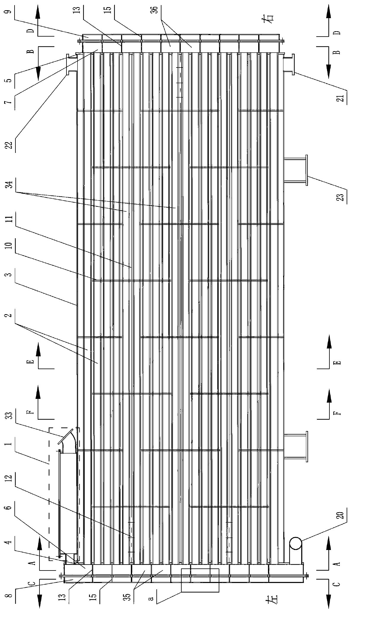
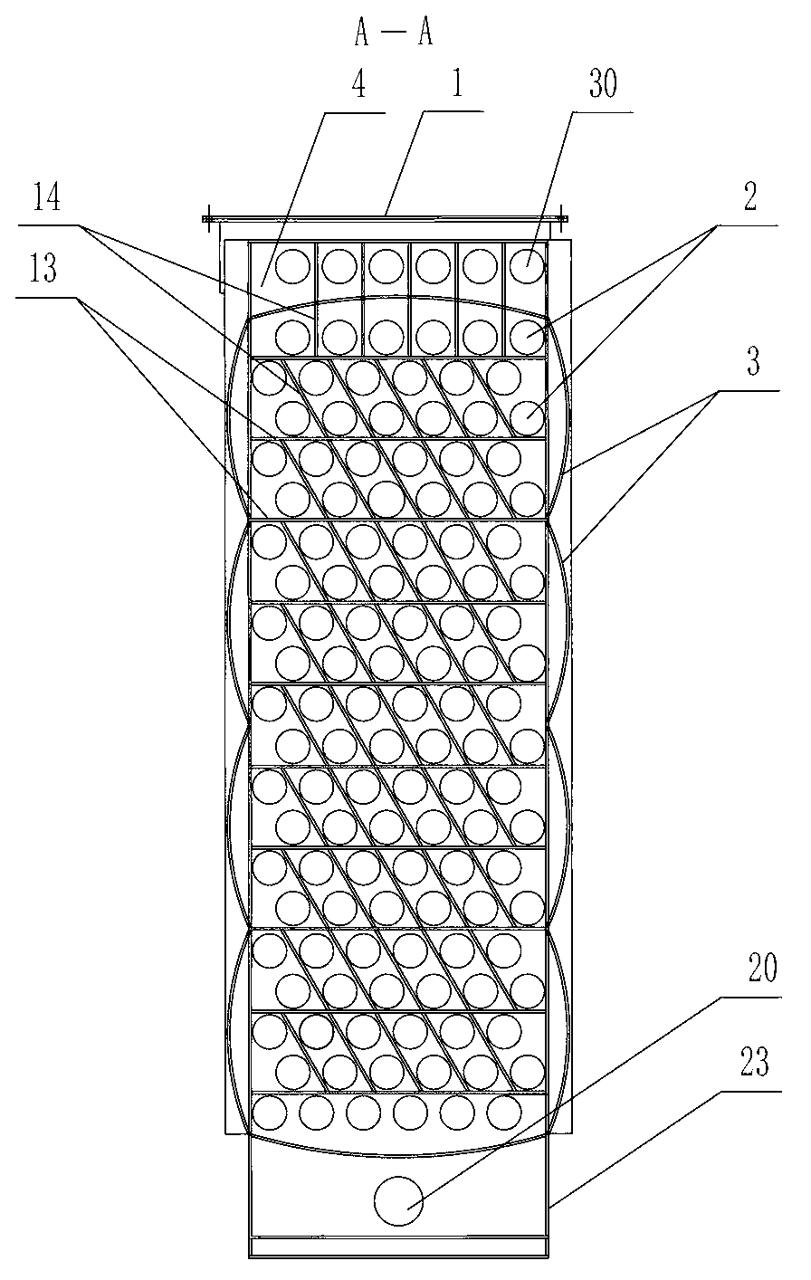
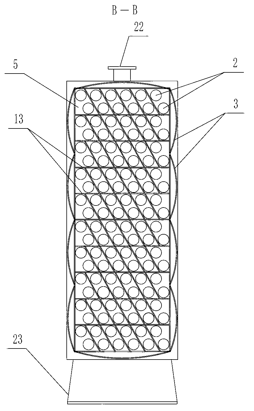
[0032] Specific implementation mode one: as Figure 1-Figure 12 As shown, the tubular heat exchange device for sewage or surface water provided with a dredging structure in this embodiment includes a flow channel separation device 1, a plurality of heat exchange tubes 2, a shell 3, a left tube plate 4, a right tube plate 5, Left header 6, right header 7, left head 8, right head 9, multiple shell baffles 10, multiple shell inner diaphragms 11, multiple transverse diaphragm holes 12, multiple headers Baffle 13, multiple header evacuation plates 14, multiple head baffles 15, multiple head evacuation plates 16, header flange 17, head flange 18, sewage or surface water outlet 20, replacement Heat medium inlet 21, heat exchange medium outlet 22, shell side area 34, left tube side area 35 and right tube side area 36; the flow channel separation device 1 includes a flow channel separation shell 24, a plurality of flow channel separation plates 25. Multiple separation flow channels 26...
specific Embodiment approach 2
[0033] Specific implementation mode two: as Figure 12 As shown, the tubular heat exchange device for sewage or surface water provided with a dredging structure described in Embodiment 1 starts from the flow channel separation inlet 28 to the first flow channel separation inner port 27 to the last flow channel separation The distance from the inner port 27 to the flow channel separation short tube 30 increases gradually in sequence, and the distance increased each time is 5mm-500mm.
specific Embodiment approach 3
[0034] Specific implementation mode three: as Figure 12 As shown, the tubular heat exchange device for sewage or surface water provided with a dredging structure as described in the second specific embodiment starts from the flow channel separation inlet 28 to the first flow channel separation inner port 27 to the last flow channel separation The distance from the inner port 27 to the flow channel separation short tube 30 increases gradually in sequence, and the distance increased each time is 50mm-200mm.
PUM
| Property | Measurement | Unit |
|---|---|---|
| Length | aaaaa | aaaaa |
Abstract
Description
Claims
Application Information
 - R&D Engineer
- R&D Manager
- IP Professional
- Industry Leading Data Capabilities
- Powerful AI technology
- Patent DNA Extraction
Browse by: Latest US Patents, China's latest patents, Technical Efficacy Thesaurus, Application Domain, Technology Topic, Popular Technical Reports.
© 2024 PatSnap. All rights reserved.Legal|Privacy policy|Modern Slavery Act Transparency Statement|Sitemap|About US| Contact US: help@patsnap.com


