Signal detection method and circuit for high precision optics voltage transformer
An optical voltage and signal detection technology, applied in the direction of voltage/current isolation, etc., can solve the problems of poor dynamic response performance, unsatisfactory, difficult to meet switching impulse voltage, lightning pulse voltage, etc.
- Summary
- Abstract
- Description
- Claims
- Application Information
AI Technical Summary
Problems solved by technology
Method used
Image
Examples
Embodiment Construction
[0094] The present invention will be described in detail below in conjunction with the accompanying drawings and embodiments.
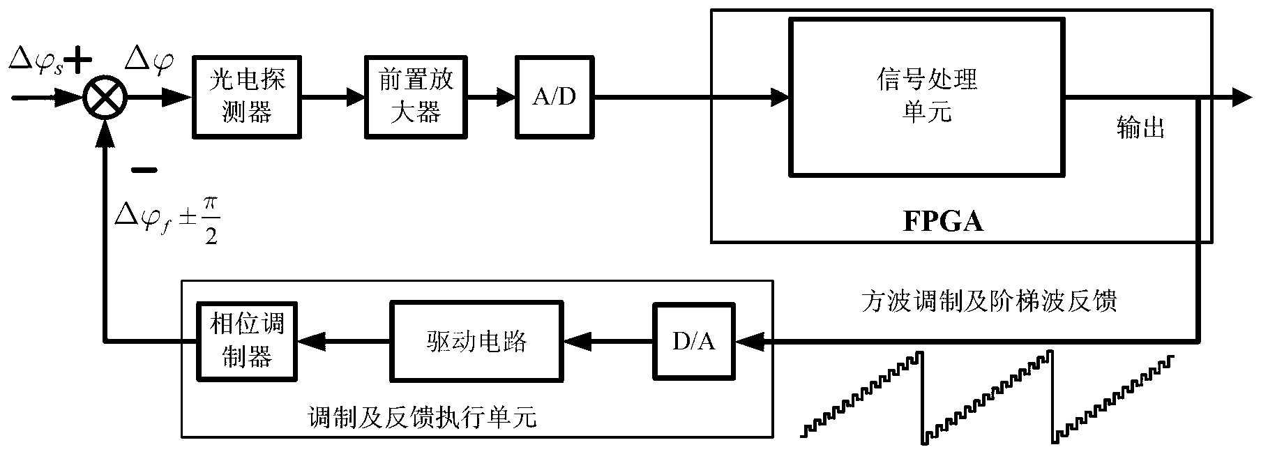
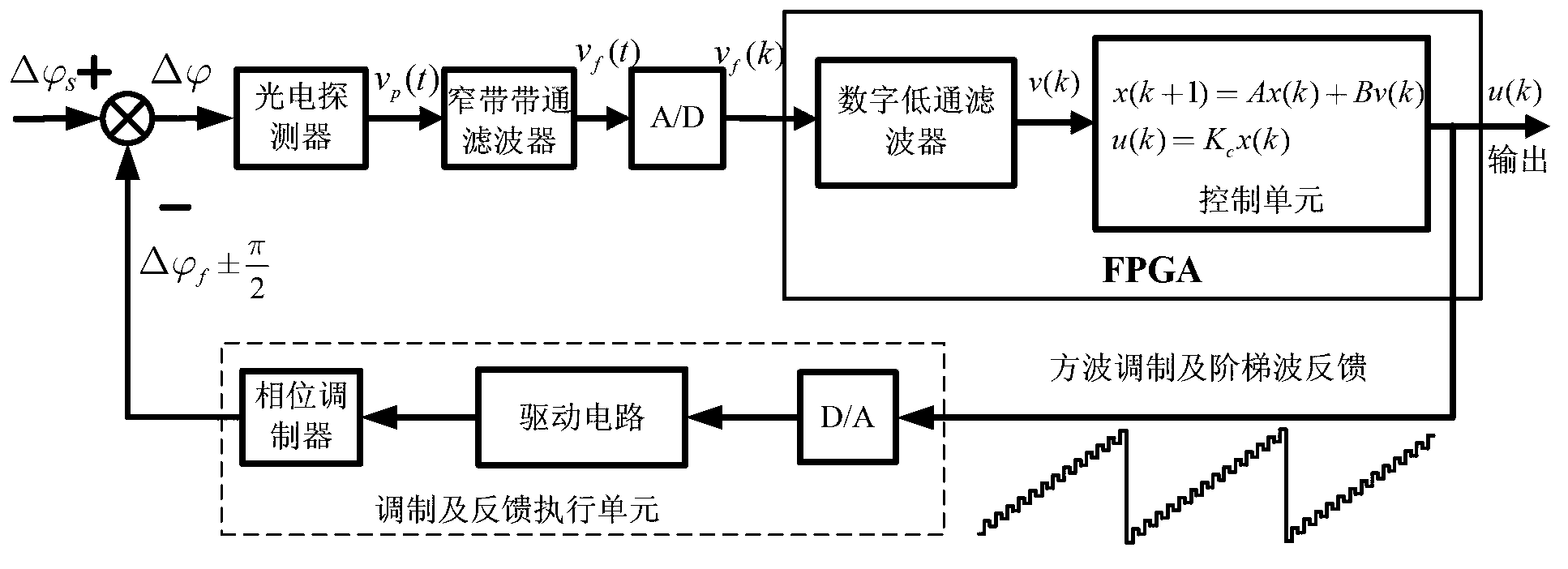
[0095] The first step is to apply high-frequency carrier technology in the optical voltage transformer to avoid 1 / f (f represents frequency) noise, that is, to migrate the closed-loop error signal to the high-frequency region through square wave modulation. As shown in equation (1), term can be regarded as a square wave amplitude modulation. Assuming a closed-loop error signal The angular frequency of ω is 1 , expressing sinω in the form of an exponential function polynomial 1 t, then there is Where t represents time, and j is a unit imaginary number, then there is formula (3).
[0096] Frequency conversion is performed on the formula (3), that is, the interference light intensity v p (t) Perform Fourier transform, formula (3) can be expressed as formula (4).
[0097] image 3 (a) shows the modulated square wave f b The spectrogram of (t) ...
PUM
 Abstract
Description
Claims
Application Information
 - R&D
- Intellectual Property
- Life Sciences
- Materials
- Tech Scout
- Unparalleled Data Quality
- Higher Quality Content
- 60% Fewer Hallucinations
Browse by: Latest US Patents, China's latest patents, Technical Efficacy Thesaurus, Application Domain, Technology Topic, Popular Technical Reports.
© 2025 PatSnap. All rights reserved.Legal|Privacy policy|Modern Slavery Act Transparency Statement|Sitemap|About US| Contact US: help@patsnap.com


