Circuit breaker capable of quickly releasing

A circuit breaker and circuit technology, which is applied to circuit breaker parts, circuit breaker contacts, protective switch operation/release mechanisms, etc., can solve the problems of time delay, increased manufacturing and assembly links, and unsatisfactory operation stability, etc. problems, to achieve the effect of being conducive to manufacturing and assembly, fast tripping speed and good economy

Active Publication Date: 2015-01-07
CHANGSHU SWITCHGEAR MFG CO LTD (FORMER CHANGSHU SWITCHGEAR PLANT)
View PDF4 Cites 0 Cited by
  • Summary
  • Abstract
  • Description
  • Claims
  • Application Information

AI Technical Summary

Problems solved by technology

[0005] However, due to the fact that the above-mentioned patent application scheme has many transmission links and unsatisfactory lack of action stability, it does not have advantages compared with the traditional way of responding to action time and detecting current signal actuation, and the transmission chain That is, the transmission relationship is complex and accompanied by a certain time delay, and, due to the use of transmission rods, the manufacturing and assembly links are increased, and it has a certain impact on the cost control of industrial mass production. There is no doubt that if any If the transition part is directly unlocked by the operating mechanism of the circuit breaker actuated by the moving contact when the moving contact is repelled relative to the fixed contact, the above-mentioned shortcomings can be eliminated. However, neither the published patent nor the non-patent literature Seeing that there are corresponding technical revelations, and there are no reports of success in the industry. To this end, the applicant has made a positive attempt, and it has been proved to be very effective by experiments. The technical scheme to be proposed below is exactly here generated under the premise

Method used


Image

  • Circuit breaker capable of quickly releasing
  • Circuit breaker capable of quickly releasing
  • Circuit breaker capable of quickly releasing

Examples


Embodiment Construction

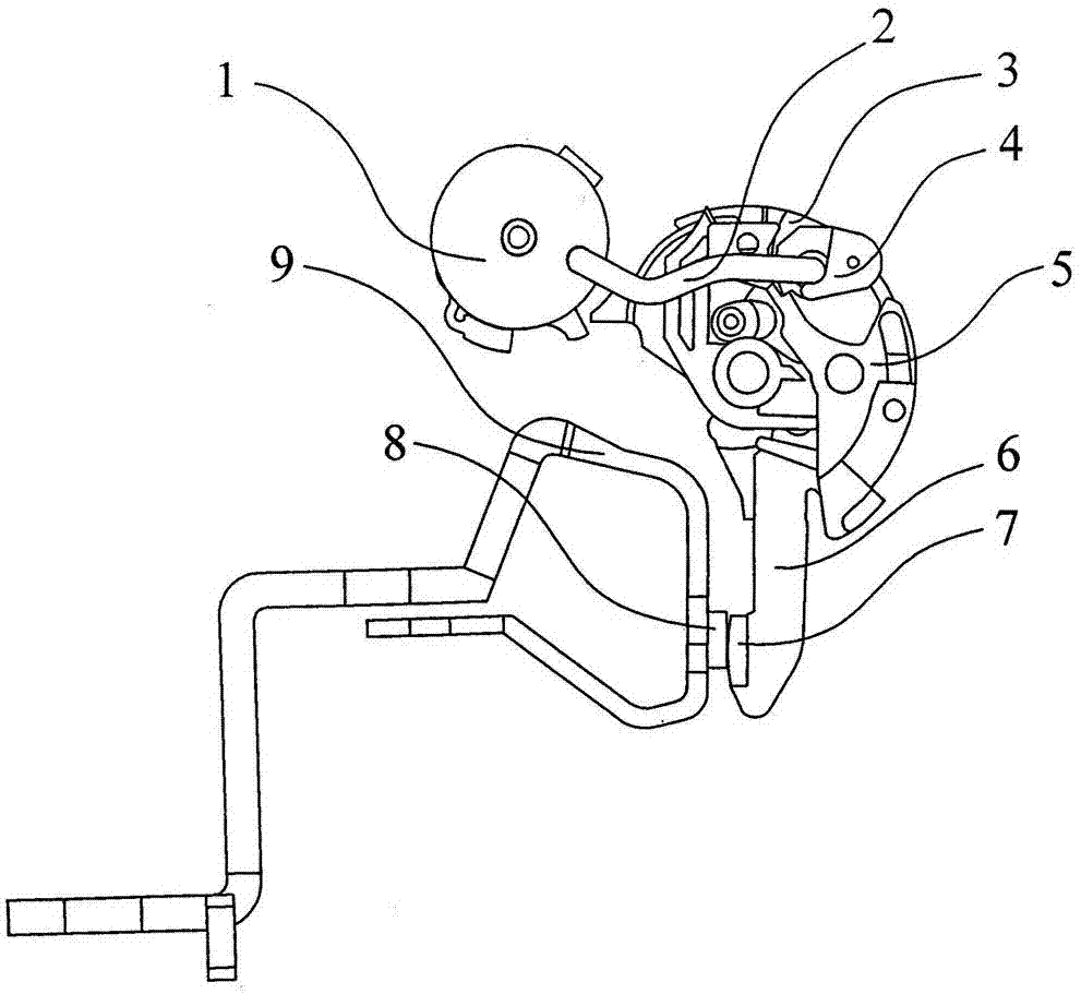
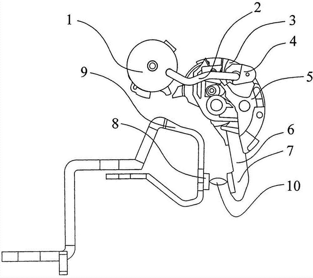
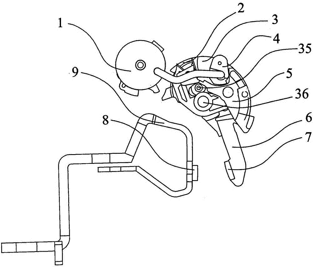
[0021] please see Figure 1 to Figure 10 . The quick-release circuit breaker of the present invention includes: a housing, a moving contact assembly accommodated in the housing, and a static contact assembly that is also accommodated in the housing and is matched with the moving contact assembly to realize circuit connection or disconnection (The static contact assembly includes a static contact 8 and a static contact guide rod 9), and also includes a handle knob assembly 1, an intermediate connecting rod 2, and a thermal-magnetic trip unit. The pivot of the handle knob assembly 1 is arranged on the shell, that is, the pivot is arranged on the Figure 10 In the first counterbore 103 shown, the intermediate connecting rod 2 is connected between the handle knob assembly 1 and the moving contact assembly. A known return spring not shown in the figure is arranged between the handle knob assembly 1 and the housing, and the return spring provides the handle knob assembly 1 with...


PUM


Abstract

The invention discloses a circuit breaker capable of quickly releasing and belongs to the technical field of low-voltage electrical appliances. The circuit breaker comprises a shell, a movable contact component, a fixed contact component, a handle knob component and a middle connection rod, the movable contact component and the fixed contact component are contained in the shell, the handle knob component is pivoted on the shell, the middle connection rod is connected between the handle knob component and the movable contact component, the movable contact component comprises a movable contact supporting part pivoted on the shell, a locking fastener pivoted on the movable contact supporting part, an unlocking part pivoted on the movable contact supporting part and a movable contact guide rod pivoted on the movable contact supporting part or the shell, and the locking fastener and the unlocking part are mutually buckled to form mechanical connection. The circuit breaker is characterized in that an unlocking part actuating flange matched with the unlocking part and used for actuating the unlocking part to move is formed by extending at a position corresponding to the unlocking part and on the movable contact guide rod. The circuit breaker capable of quickly releasing has the advantages of quickness in releasing, simple structure, conduciveness to manufacturing and assembly and high economical efficiency.

Description

technical field [0001] The invention belongs to the technical field of low-voltage electrical appliances, and in particular relates to a quick-release circuit breaker. Background technique [0002] The automatic tripping technology of low-voltage circuit breakers is mainly used to automatically trip the circuit breaker when an overload or short-circuit fault occurs, thereby protecting the low-voltage power distribution network and the load connected to the circuit breaker. The automatic tripping device for overload fault protection is generally a thermal release, and the main component is a heat-sensitive bimetallic strip, while the automatic tripping device for short-circuit fault protection is generally a magnetic release, including a solenoid electromagnet and a clapper. In addition, there is an electronic trip device for customizing more abundant protection functions. [0003] In particular, for current-limiting circuit breakers under short-circuit and high-current faul...

Claims


Application Information

Patent Timeline
Patent Type & Authority Patents(China)
IPC IPC(8): H01H71/10H01H73/04
Inventor 顾建青谢心意王铖陈红影刘洪武
Owner CHANGSHU SWITCHGEAR MFG CO LTD (FORMER CHANGSHU SWITCHGEAR PLANT)
Why Eureka
Try Eureka