Film-cutting machine structure

A scribing and sliding film technology, applied in electrical components, semiconductor/solid-state device manufacturing, circuits, etc., can solve the problem of uneven force on the blue film boundary, high defect rate, and inability to ensure that the wafer ring die is all tight, etc. problem, to achieve the effect of reducing die extrusion damage, improving yield and uniform force

Inactive Publication Date: 2013-04-03
WUXI RED MICROELECTRONICS CORP
View PDF3 Cites 0 Cited by
  • Summary
  • Abstract
  • Description
  • Claims
  • Application Information

AI Technical Summary

Problems solved by technology

[0002] The existing wafer ring lamination process requires employees to use a blade to draw the shape of the blue film. Since the force on the hand cannot be kept consistent at all times when manually marking the film, the force on the boundary of the blue film is uneven, which in turn makes the blue film After being tightened on the machine disk, due to the uneven force on the boundary of the blue film, it is impossible to ensure that all the grains on the wafer ring are tightened, and the grains on the wafer ring are not tightened, causing the grains to squeeze. Pressure damage, high defect rate

Method used


Image

  • Film-cutting machine structure
  • Film-cutting machine structure

Examples


Embodiment Construction

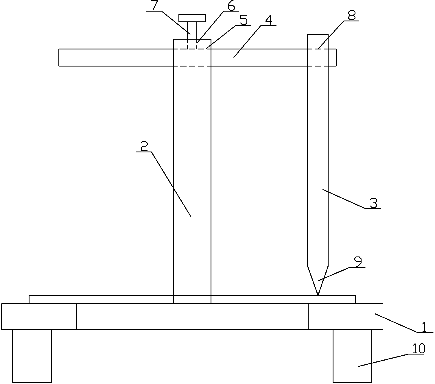
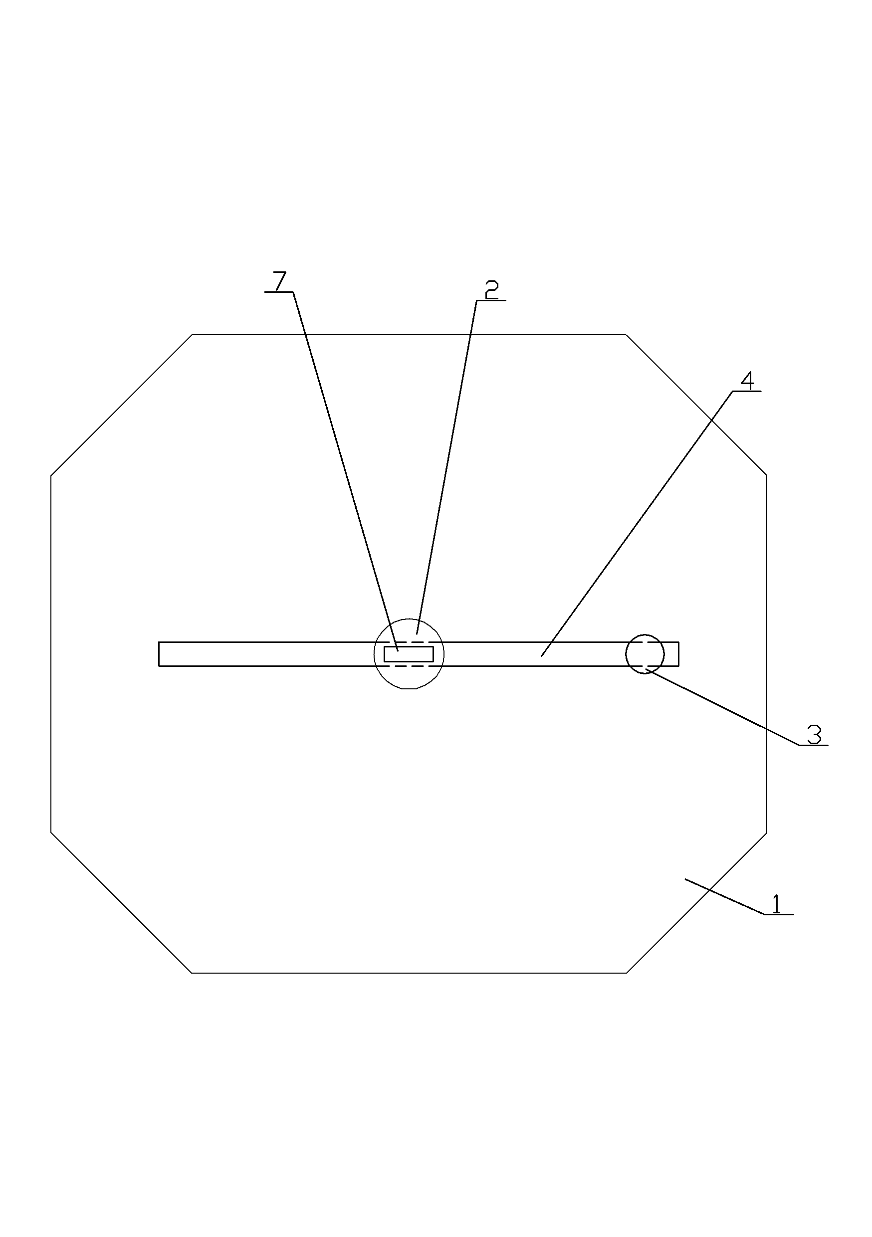
[0009] See figure 1 , figure 2 , which includes a base 1, a central shaft 2, the central shaft 2 is vertically inserted in the center of the base 1, it also includes a synovial knife 3, a synovial knife horizontal shaft 4, and the upper end of the central shaft 2 is provided with a through radial hole 5. The horizontal axis 4 of the synovial film knife runs through the radial hole 5 and then is arranged parallel to the plane of the base 1. There is a vertical limit threaded hole 6 in the center of the top of the central shaft 2, and the limit threaded hole 6 is connected to the radial hole 5. The limit screw 7 is threadedly connected to the limit threaded hole 6, and the lower end of the limit screw 7 is tightly pressed against the horizontal axis 4 of the synovial knife. The synovial knife 3 is arranged perpendicular to the plane of the base 1. The upper end of the film knife 3 radially positions the hole 8 , and the knife head part 9 of the synovial film knife 3 faces the ...


PUM


Abstract

The invention provides a film-cutting machine structure which can ensure evenly strength receiving when cutting the film, thereby reducing the amount of incompact crystal grains on a machine disc after sticking a blue film on a crystal ring, then reducing the pressing damage of the crystal caused by incompact and improving the yield. The film-cutting machine structure comprises a base seat and a central rotating shaft, the central rotating shaft is vertically plug-in mounted in the centre of the base seat, and the film-cutting machine structure is characterized in that a film sliding knife and a film sliding knife cross shaft are also included, a penetrating radial hole is formed on the upper end of the central rotating shaft, the film sliding knife cross shaft penetrates the radial hole and is arranged in parallel with the flat surface of the base seat, the central of the top portion of the central rotating shaft is opened with a vertical limit threaded hole, the limit threaded hole is communicated with the radial hole, and a limit threaded rod is connected with the limit threaded hole, the lower end of the limit threaded rod is pressed on the film-cutting knife cross shaft, the film-cutting knife is vertically arranged on the flat surface of the base, and one end of the film-cutting knife cross shaft penetrates the radial hole formed on the upper end of the film sliding knife.

Description

technical field [0001] The invention relates to the technical field of wafer ring film sticking for semiconductor processing, in particular to the structure of a film scriber. Background technique [0002] The existing wafer ring lamination process requires employees to use a blade to draw the shape of the blue film. Since the force on the hand cannot be kept consistent at all times when manually marking the film, the force on the boundary of the blue film is uneven, which in turn makes the blue film After being tightened on the machine disk, due to the uneven force on the boundary of the blue film, it is impossible to ensure that all the grains on the wafer ring are tightened, and the grains on the wafer ring are not tightened, causing the grains to squeeze. Pressure damage, high defect rate. Contents of the invention [0003] In view of the above problems, the present invention provides a film scribing machine structure, which ensures that the force is even when scribin...

Claims


Application Information

Patent Timeline
IPC IPC(8): H01L21/67
Inventor 夏金平
Owner WUXI RED MICROELECTRONICS CORP
Why Eureka
Try Eureka