Patch radio-frequency antenna

A radio frequency antenna and patch technology, which is applied in the field of intelligent personnel or object positioning systems, can solve the problems of prolonged development time, easy deformation, and high cost, and achieve strong product adaptability, save development time, and solve the effects of easy deformation

Inactive Publication Date: 2013-04-03
邹志荣
View PDF7 Cites 3 Cited by
  • Summary
  • Abstract
  • Description
  • Claims
  • Application Information

AI Technical Summary

Problems solved by technology

[0003] At present, the patch RF antenna on the market adopts an integral base. The size of the base and the position of the pad on the base cannot be adjusted. One base specification can only produce patch RF antennas of one size, and different sizes can be produced. SMD RF antennas need to redesign the base and remake the base mold every time, resulting in higher costs and longer development time; at the same time, because the base is generally made of

Method used


Image

  • Patch radio-frequency antenna
  • Patch radio-frequency antenna
  • Patch radio-frequency antenna

Examples


Embodiment Construction

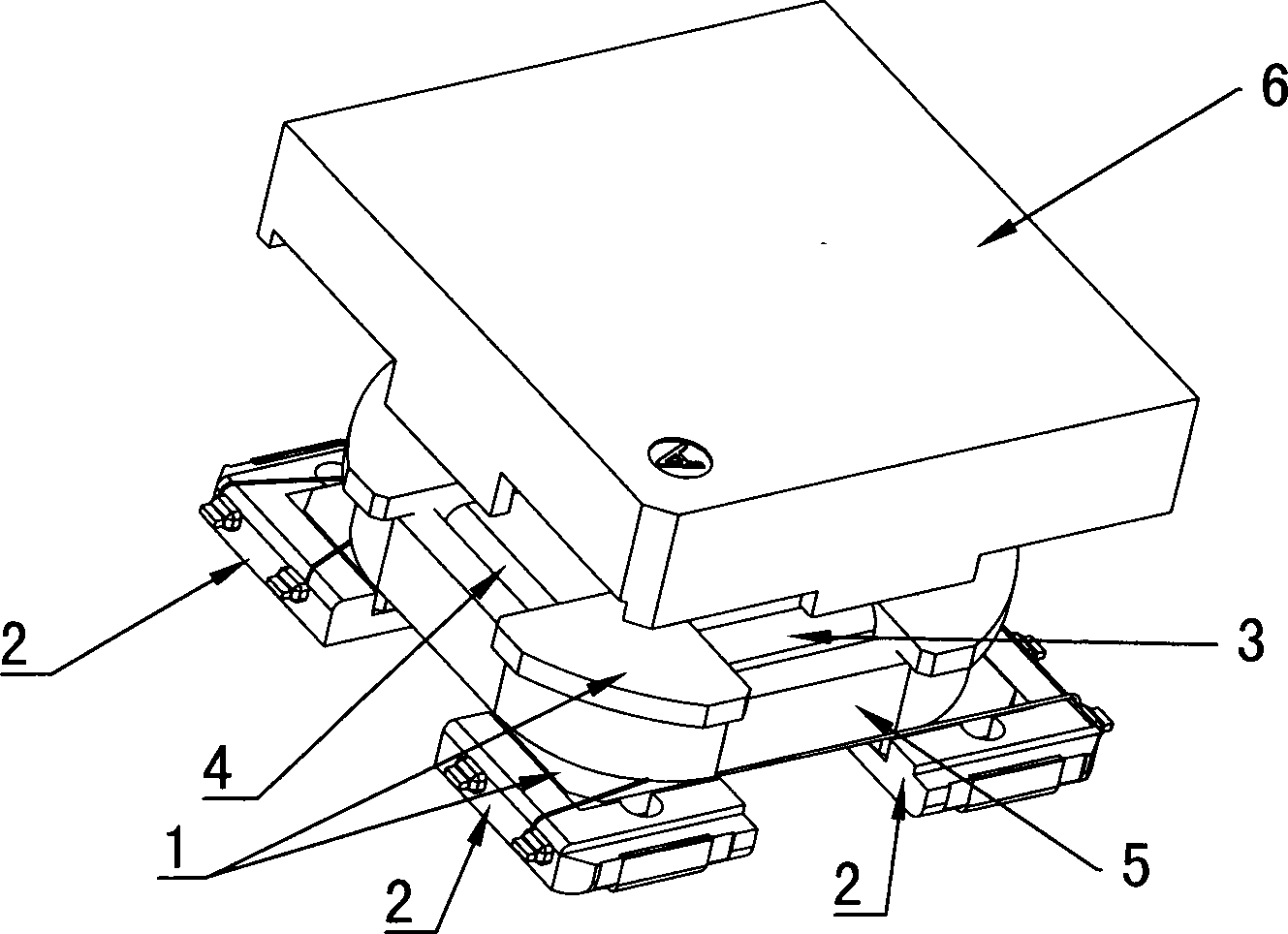
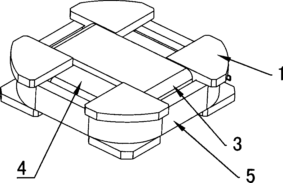
[0018] Such as Figures 1 to 5 As shown, the distributed base patch radio frequency antenna in the present invention includes: a magnetic core 1, and bases 2 respectively fixed on the four end corners of the magnetic core 1; each base 2 is an independent component.

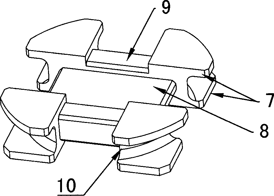
[0019] The magnetic core 1 is I-shaped, and the magnetic core 1 is provided with an X-axis winding groove 8 for winding the X-axis coil 3 and a Y-axis winding groove 9 for winding the Y-axis coil 4, wherein, X 1. The winding direction of the Y-axis coil is vertically intersected; the four end corners of the magnetic core 1 are provided with arc-shaped slots 10, and a Z-axis coil 5 is wound on each arc-shaped slot 10, and the winding of the Z-axis coil 5 The control direction is perpendicular to the X and Y axis coils at the same time.

[0020] The plastic base 2 is provided with base slots 13, and the bottom surface of the four corners of the magnetic core 1 is respectively bonded to the four base slots 13 by glu...


PUM


Abstract

The invention relates to a patch radio-frequency antenna with distributed bases. The patch radio-frequency antenna comprises H-shaped magnetic cores, each magnetic core is provided with an X-axis coiling groove used for coiling an X-axis coil and a Y-axis coiling groove used for coiling a Y-axis coiling groove, and the coiling directions of the X-axis coil and the Y-axis coil are perpendicularly crossed. Four end corners of the magnetic cores are provided with arc-shaped grooves, a Z-axis coil is coiled in the arc-shaped grooves, and the coiling direction of the Z-axis coil is perpendicular to that of the X-axis coil and the Y-axis coil. The bases are respectively fixed on the four end corners of the magnetic cores and are independent components. The bases are fittingly used with the magnetic cores in different size, so that the patch radio-frequency antenna with the distributed bases can be formed in different size. The patch radio-frequency antenna in different size can be manufactured by designing the magnetic cores in different size to match with the original bases without needs to redesign the bases, so that the patch radio-frequency antenna is high in applicability, and cost and time for development of the patch radio-frequency antenna are reduced and saved.

Description

technical field [0001] The invention relates to a distributed base patch radio frequency antenna, which is applied to occasions requiring low-frequency wake-up signal transmission, such as keyless entry systems for cars, intelligent personnel or object positioning systems. Background technique [0002] SMD RF antennas are mainly used in today's electronic technology field that requires low-frequency wake-up signal transmission, such as car keyless entry systems, intelligent door opening systems, intelligent personnel or object positioning systems, etc., and the size of such products in various fields There are strict requirements on the size, so patch RF antennas of different sizes need to be designed for different fields. [0003] At present, the patch RF antenna on the market adopts an integral base. The size of the base and the position of the pad on the base cannot be adjusted. One base specification can only produce patch RF antennas of one size, and different sizes can...

Claims


Application Information

Patent Timeline
IPC IPC(8): H01Q1/12H01Q7/06
Inventor 邹志荣
Owner 邹志荣
Why Eureka
Try Eureka