Escapement system for a timepiece

A technology of escapement fork and escapement wheel, applied in the field of escapement system, which can solve the problems of low mechanical strength and achieve the effects of easy molding, energy increase and good energy recovery coefficient

Inactive Publication Date: 2013-04-03
THE SWATCH GRP RES & DEVELONMENT LTD
View PDF9 Cites 8 Cited by
  • Summary
  • Abstract
  • Description
  • Claims
  • Application Information

AI Technical Summary

Problems solved by technology

A disadvantage of components made of crystalline materials is their low mechanical strength when high stresses are applied
So there is a process of teeth pushing and sliding to cause the gear train to turn

Method used


Image

  • Escapement system for a timepiece
  • Escapement system for a timepiece

Examples


Embodiment Construction

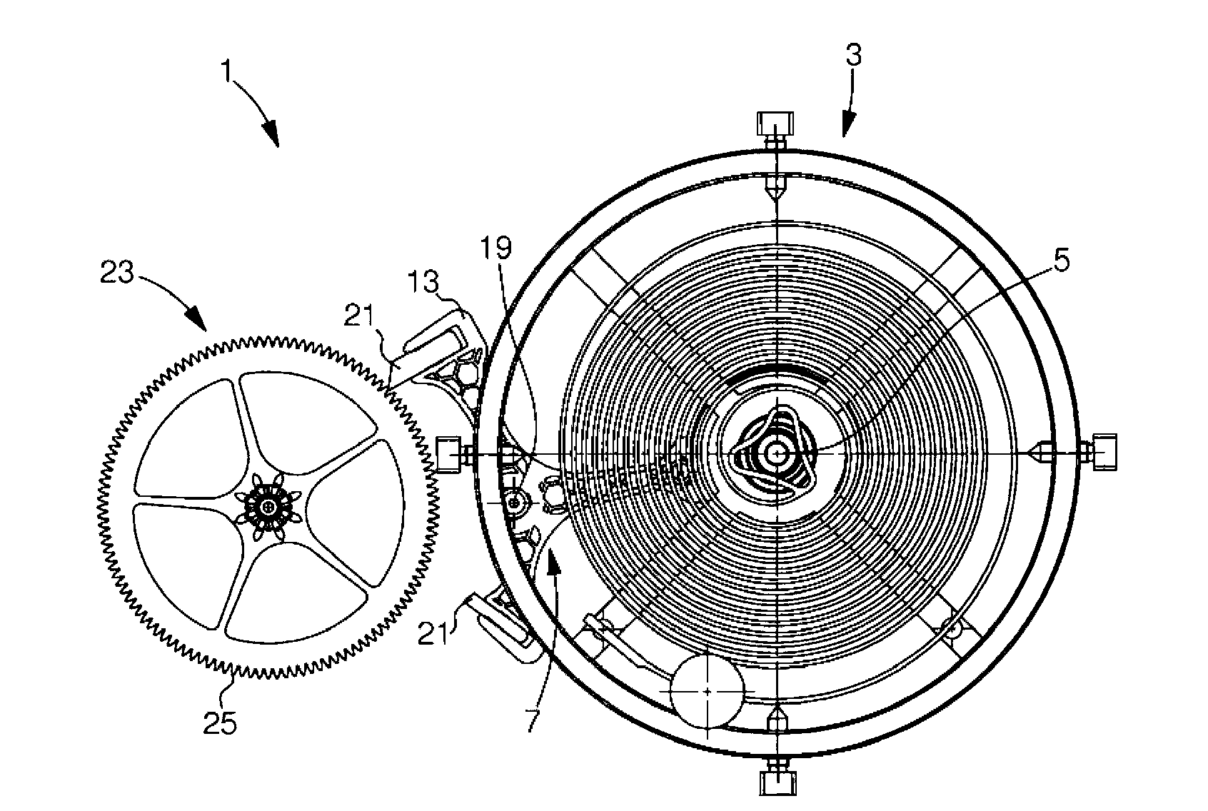
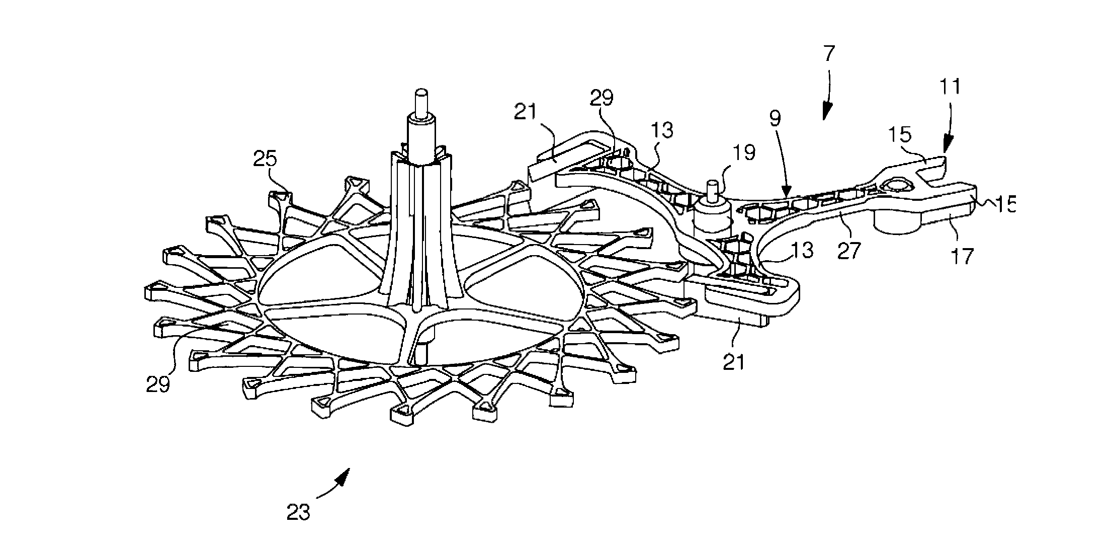
[0035] figure 1 with figure 2 The escapement 1 is shown with a resonator 3 , ie a balance with sprung hair. In general, resonator 3 cooperates with escapement 1 with the assistance of disc 5 mounted on the axis of the balance wheel. Escapement 1 consists of a main face (see figure 1 ) form the Swiss anchor pallet fork 7 . The Swiss anchor 7 is mainly formed by a rod 9 connecting a prong 11 and an arm 13 . Prong 11 comprises two cornes 15 facing each other, below which are mounted prong pins 17 which engage respectively with pins fixed to said disc 5 of the axis of the balance wheel. Cooperate with the bottom of said disc 5.

[0036]Between the two arms 13 , the lever 9 receives an arbor 19 for the rotatable mounting of the anchor between the bridges and the baseplate of the movement. Finally, fitted on each arm 13 is a fork 21 intended to come into contact with escape wheel 23 through its teeth 25 . As an example, the prong tiles may be formed from synthetic rubies. O...


PUM


Abstract

The invention relates to an escapement system (1). This system comprises a pallet (7) equipped with a fork intended to collaborate with a pin mounted on a plate (5), and with a rod comprising arms intended to accept pallet stones (21) so as to collaborate with at least one escapement wheel (23). Part of the escapement system is made of an at least partially amorphous metal alloy.

Description

technical field [0001] The invention relates to an escapement system. The escapement system comprises an anchor pallet fitted with a munie head for cooperating with a pin mounted on a disc, and a rod comprising an arm for receiving a fork stone in order to communicate with at least one Escape wheel cooperation. [0002] The technical field of the invention is that of precision mechanics, and more particularly of watchmaking. Background technique [0003] A timepiece includes an energy source, such as a barrel, that supplies energy to parts and especially a gear train. These gear trains cooperate with the escapement system via the escape wheel. The rotation of the escape wheel is regulated by the anchor pallet fork of the escapement system, and the shock of the escapement system is provided by the balance with hairspring. The escapement system includes an anchor mounted for pivoting on an axis. The anchor consists of a rod fitted at a first end with a prong for cooperati...

Claims


Application Information

Patent Timeline
Patent Type & Authority Applications(China)
IPC IPC(8): G04B15/14
CPCG04B15/00G04B15/14
Inventor C·沙邦Y·温克勒M·韦拉尔多
Owner THE SWATCH GRP RES & DEVELONMENT LTD
Why Eureka
Try Eureka