Pneumatic hacksawing machine and pneumatic control system of pneumatic hacksawing machine
A hacksaw machine and pneumatic technology, applied in the field of pneumatic hacksaw machines and their pneumatic control systems, can solve the problems of inability to cut metal materials, high requirements on machining precision of parts, increase labor intensity of workers, etc., and achieve high practical value and high work efficiency. , The effect of cutting a wide range of materials
- Summary
- Abstract
- Description
- Claims
- Application Information
AI Technical Summary
Problems solved by technology
Method used
Image
Examples
Embodiment 1
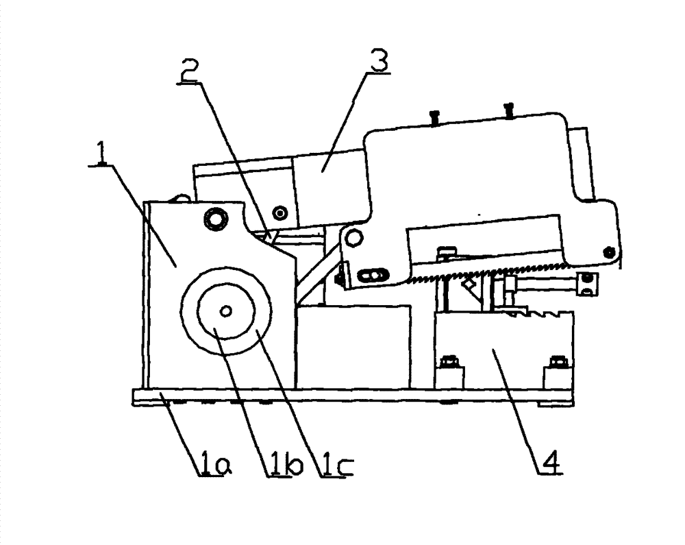
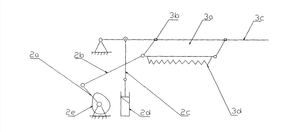
[0013] see figure 1 and figure 2 , a kind of pneumatic bow sawing machine provided by the present invention comprises a power mechanism 1, a power feed mechanism 2, a cutting mechanism 3, and a clamping mechanism 4 arranged below the cutting mechanism 3 for clamping metal materials; the power mechanism 1 includes an air motor 1b set on the frame 1a, one end of the air motor 1b is provided with a reducer 1c, the output shaft of the reducer 1c is matched with the crank 2a in the power feeding mechanism 2 through a key, and the other end of the crank 2a One end is hinged on the connecting rod I 2b, and the other end of the connecting rod I 2b is hinged with the knife rest 3a in the cutting mechanism 3, and the knife rest 3a is connected by a slide block 3b to realize reciprocating movement on the saw blade guide rail 3c, The bottom end of the knife rest 3a is equipped with a cutting saw blade 3d, and the knife rest 3a is driven by the air motor 1b to realize the reciprocating o...
Embodiment 2
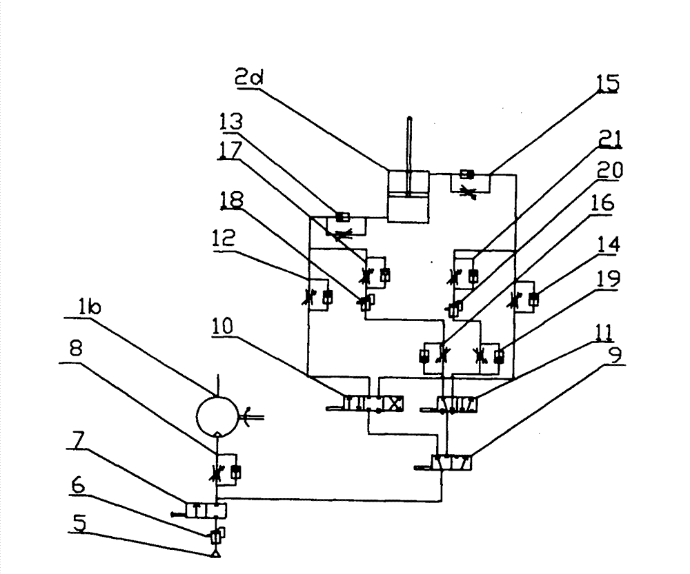
[0015] This embodiment is an explanation of the pneumatic control mode of the present invention:
[0016] see image 3 , the pneumatic control system includes an air source 5, the air source 5 is respectively connected to the air motor 1b provided with an air motor speed regulating switch 8 through a pressure reducing valve 16 and an air source switch 7 in turn, and the switch is realized by a switching valve 9 On the cylinder control circuit, the cylinder control circuit includes a quick lift valve 10 connected to the switch valve 9 and a stroke reversing valve 11. When the switch valve 9 is turned to the left, the quick lift valve 10 formed The working circuit starts to work. When the switching valve 9 is switched to the right position, the stroke reversing working circuit formed by the stroke reversing valve 11 starts to work; a check joint is connected to a circuit formed by the fast lifting valve 10 and the cylinder 2d. Throttle valve I 12, one-way throttle valve I 12 is...
PUM
 Abstract
Description
Claims
Application Information
 - R&D Engineer
- R&D Manager
- IP Professional
- Industry Leading Data Capabilities
- Powerful AI technology
- Patent DNA Extraction
Browse by: Latest US Patents, China's latest patents, Technical Efficacy Thesaurus, Application Domain, Technology Topic, Popular Technical Reports.
© 2024 PatSnap. All rights reserved.Legal|Privacy policy|Modern Slavery Act Transparency Statement|Sitemap|About US| Contact US: help@patsnap.com


