Supercharge Your Innovation With Domain-Expert AI Agents!

Hole puncher

A puncher and hole shaft technology, applied in metal processing, etc., can solve the problems of high equipment cost, complicated operation, and complicated punching machine, and achieve the effects of low cost, labor-saving punching, and high punching efficiency

Inactive Publication Date: 2013-04-10
张庭瑞
View PDF0 Cites 10 Cited by
  • Summary
  • Abstract
  • Description
  • Claims
  • Application Information

AI Technical Summary

Problems solved by technology

Existing punching equipment is various, but, the punching machine that has is very complicated, and equipment cost is higher, and operation is also more complicated; I can't help

Method used


Image

  • Hole puncher
  • Hole puncher
  • Hole puncher

Examples


Embodiment Construction

[0015] The present invention will be described in further detail below in conjunction with the accompanying drawings.

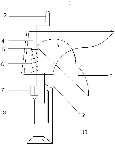
[0016] Such as figure 1 As shown, the puncher provided by the present invention includes a fixed handle 1, a movable handle 2, a handle 3, a punching shaft 4, a shaft chuck 5, a spring 6, a cone holder 7, a cone 8, and a support plate 9 And movable baffle 10. The upper end of the punching shaft 4 is fixedly connected with the rocker 3, the middle part of the punching shaft 4 is provided with a shaft chuck 5 and is fixed as one with the punching shaft 4, and the lower end of the punching shaft 4 connects the cone holder 7. The cone head holder 7 fixes the cone head 8 by screws or clips. A spring 6 is arranged on the punching shaft 4 between the shaft chuck 5 and the fixed handle 1 . The top of the movable handle 2 contacts the shaft chuck 5 . The fixed handle 1 is connected to the support plate 9, and the support plate 9 is movably connected to the movable...


PUM


Abstract

The invention discloses a hole puncher, which comprises a fixed handle, a movable handle, a crank, a hole punching shaft, a shaft chuck, a spring, a conical head fixer, conical heads, a support plate and a movable baffle plate. According to the hole puncher, punching tasks can be completed easily by using hand force when hole punching files are not too thick; and if the hole punching files are thicker, and hand force is insufficient, the crank can be rotated easily for assisting in finishing hole punching. In the hole puncher, a plurality of kinds of conical heads are available for replacing, so that the requirement of punching of different holes can be met, and the manual punching force can be reduced by replacing the conical heads. The hole puncher disclosed by the invention has the advantages of simple structure, low manufacturing cost, saving in punching force, higher punching efficiency and capability of punching a plurality of holes as required.

Description

technical field [0001] The invention relates to a punching device for stationery, in particular to a punching device for binding multiple documents or bills. Background technique [0002] In the processing of office documents, it is often necessary to punch and bind the documents. Existing punching equipment is various, but, the punching machine that has is very complicated, and equipment cost is higher, and operation is also more complicated; There is nothing I can do to help. Contents of the invention [0003] In order to solve the deficiencies of the prior art, the present invention provides a puncher with simple structure, convenient and fast punching operation, and capable of punching thicker documents. [0004] The technical scheme adopted in the present invention is: [0005] A hole puncher includes a fixed handle, a movable handle, a crank, a punching shaft, a shaft chuck, a spring, a cone head fixer, a cone head, a support plate, and a movable baffle. Wherein ...

Claims


Application Information

Patent Timeline
Patent Type & Authority Applications(China)
IPC IPC(8): B26F1/32
Inventor 张庭瑞
Owner 张庭瑞
Features
  • R&D
  • Intellectual Property
  • Life Sciences
  • Materials
  • Tech Scout
  • Unparalleled Data Quality
  • Higher Quality Content
  • 60% Fewer Hallucinations
Learn More