Rotary drum grille type packing device

A technology of drum and grid, which is applied in the field of drum grid type packing device, which can solve the problems of inability to finely control the amount and position of powder feeding, inconsistent powder density, and low production efficiency, so as to achieve smoothness and uniformity , No powder leakage, small footprint

Active Publication Date: 2013-04-10
佛山市光华智能设备有限公司
View PDF7 Cites 7 Cited by
  • Summary
  • Abstract
  • Description
  • Claims
  • Application Information

AI Technical Summary

Problems solved by technology

This kind of filling equipment has many technical defects, including: 1. The amount and location of powder feeding cannot be finely controlled, so that the powder falling onto the powder carrier is uneven and is filled into various positions in the mold cavity The powder density is inconsistent; 2. During the filling process, the powder is pushed forward in a straight line, and there will be more material leakage; 3. The floor area is large, the filling time is long, the production efficiency is low, and the equipment cost is high; 4. It is impossible to evenly fill products with large specifications such as 1300×1900 or more

Method used


Image

  • Rotary drum grille type packing device
  • Rotary drum grille type packing device
  • Rotary drum grille type packing device

Examples


Embodiment 1

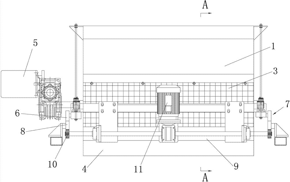
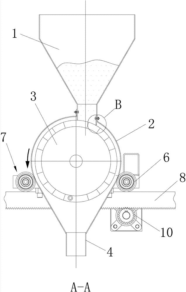
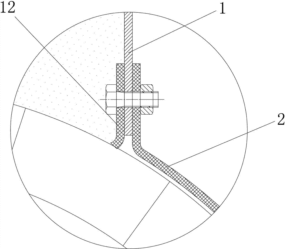
[0022] Embodiment 1: see attached figure 1 To attach Figure 4 As shown, the drum grid type filling device described in this embodiment includes a storage hopper 1, a dust cover 2, a drum 3 with a loading grid on the outer peripheral surface, a blanking hopper 4, and a drive unit 5 (specifically variable frequency motor), wherein, the drum 3 is horizontally arranged in the dust cover 2, and is driven to rotate by the drive unit 5 located on one side of its shaft end, and the grille 3 and the drive unit 5 are connected by a shaft or a sprocket chain The transmission is carried out, and at the same time, the grid shape of the loading grid on the outer peripheral surface of the drum 3 is rectangular; the storage hopper 1 is arranged adjacent to the top of the drum 3, and is fixedly connected with the dust cover 2, and the outlet of the storage hopper 1 The material opening is set on the side deviating from the axis of the drum 3 to ensure that there is no free fall of the powder...

Embodiment 2

[0023] Embodiment 2: see attached Figure 5 As shown, the difference from Embodiment 1 is that the grid shape of the loading grid in this embodiment is a regular hexagon.

Embodiment 3

[0024] Embodiment 3: see attached Figure 6 As shown, the difference from Embodiment 1 is that the grid shape of the loading grid in this embodiment is circular.

[0025] After adopting the above scheme, the present invention can ensure accurate, uniform, smooth and reliable powder filling action. Compared with the prior art, the present invention has a compact and simple structure, a small footprint, less mechanical action during the filling process, and high efficiency. , no powder leakage, easy to adjust the amount of powder input, wide application range, can greatly reduce manufacturing and maintenance costs, it is worth promoting.


PUM


Abstract

The invention provides a rotary drum grille type packing device, which comprises a storage hopper, a dust cover, a rotary drum, a blanking hopper and a driving unit, wherein a material loading grille is arranged on the peripheral surface of the rotary drum; the rotary drum is transversely arranged in a dust cover and is driven by the driving unit positioned on one side of the shaft end of the rotary drum to rotate; the storage hopper is closely arranged above the rotary drum and is fixedly connected with the dust cover, and meanwhile, the discharge port of the the storage hopper is in clearance fit with the material loading grille on the peripheral surface of the rotary drum; the blanking hopper is arranged below the rotary drum, and the feed port of the blanking hopper corresponds to the rotary drum; and meanwhile, the blanking hopper is fixedly connected with the dust cover. After the rotary drum grille type packing device adopts the scheme, the material loading grille on the peripheral surface of the rotary drum is utilized to convey power and fix the powder in a set position, then the rotary drum puts the constant weight of powder on a die cavity or other powder carriers at a constant rotation speed, and therefore the smoothness and the uniformity of powder putting are realized.

Description

technical field [0001] The invention relates to the technical field of production fillers for building chemical materials such as ceramic bricks and foam bricks, in particular to a drum grid type filler device. Background technique [0002] In the traditional filling method, it is usually completed by a linear moving filling vehicle or filling equipment, and the filling equipment is composed of a material pipe, a hopper, and a powder conveyor belt. When working, the material pipe and hopper run to the top of the conveyor belt, and the powder of different weights is controlled to fall freely onto the conveyor belt by controlling the switch of the valve, and then the powder is freely dropped to the powder carrier (such as a grid) through the operation of the belt. or blank pad), or directly fill the powder in the hopper into the powder carrier (such as grid or blank pad) through the feeding tube, and then send the powder to the cavity of the mold by a feeding cart or other cir...

Claims


Application Information

Patent Timeline
IPC IPC(8): B28B13/02
Inventor 霍丰源毛新陈晓松
Owner 佛山市光华智能设备有限公司
Why Eureka
Try Eureka