Heat radiation device

A heat dissipation device and heat sink technology, which is applied in the direction of lighting devices, cooling/heating devices of lighting devices, lighting and heating equipment, etc., can solve the problem that the heat dissipation area is not maximized, achieve long service life, and expand the heat dissipation area , High heat dissipation effect

Inactive Publication Date: 2013-04-10
阳玉欣
View PDF2 Cites 4 Cited by
  • Summary
  • Abstract
  • Description
  • Claims
  • Application Information

AI Technical Summary

Problems solved by technology

In the existing heat sink, its surface is made into a fin shape, and the fins are distributed in parallel to increase the heat dissipation area of ​​the heat sink and improve the heat dissipation efficiency, but the heat dissipation area has not been maximized, and only by relying on It is very limited to increase the heat dissipation area to improve the heat dissipation efficiency, and its structure needs to be improved

Method used


Image

  • Heat radiation device

Examples


Embodiment Construction

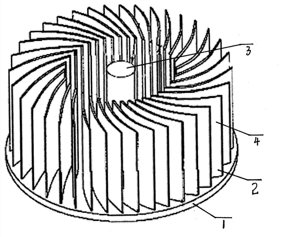
[0015] Such as figure 1 As stated, a heat dissipation device of the present invention includes an LED (not shown in the figure), a copper-aluminum substrate for carrying and installing the LED, and a heat sink arranged under the copper-aluminum substrate, (shown in the figure as an upside-down state of the heat dissipation device ) The heat sink includes an annular base and an axis column arranged in the base, the top surface of the base extends upwards to form a number of heat dissipation fins, the heat dissipation fins are in a streamlined arc shape, and the space between the heat dissipation fins A gap is formed.

[0016] The heat dissipation device of the present invention also includes a liquid storage tank and an electric pump. The axial column is a hollow cylinder, and the interior of the axial column is divided into a liquid inlet chamber and a liquid outlet chamber, wherein the liquid inlet chamber is connected to the liquid storage tank through the liquid inlet pipe....


PUM

PropertyMeasurementUnit
Arc angleaaaaaaaaaa

Abstract

The invention discloses a heat radiation device, which comprises an LED (light emitting diode), a copper aluminum base plate and a heat radiator, wherein the copper aluminum base plate is used for carrying and installing the LED, the heat radiator is arranged under the copper aluminum base plate and comprises an annular base and an axis post arranged in the base, the top surface of the base upwards extends for forming a plurality of heat radiation fins, the heat radiation fins are in outer flow line type arc shapes, and in addition, gaps are formed among the heat radiation fins. The base formed by a plurality of circularly surrounding heat radiation fins in the outer flow line type arc shapes is adopted, the heat radiation area of the heat radiation device is greatly enlarged, in addition, the axis post simultaneously has the heat radiation effect, the heat radiation efficiency is high, the evanescence of the LED lamp is delayed, and the service life is long.

Description

technical field [0001] The invention relates to the technical field of LED lighting, in particular to a heat dissipation device for an LED lamp with good heat dissipation efficiency. Background technique [0002] With the in-depth application of high-power LED lights, a technical bottleneck has arisen, that is, light decay, that is, the heat dissipation problem of LED lights. The existing heat dissipation method is mainly to transfer the heat generated by the LED to the heat sink through the copper-aluminum substrate. On the radiator, the heat is dissipated into the air by the radiator. In the existing heat sink, its surface is made into a fin shape, and the fins are distributed in parallel to increase the heat dissipation area of ​​the heat sink and improve the heat dissipation efficiency, but the heat dissipation area has not been maximized, and only by relying on It is very limited to increase the heat dissipation area to improve the heat dissipation efficiency, and its ...

Claims


Application Information

Patent Timeline
IPC IPC(8): F21V29/02F21Y101/02F21V29/56F21V29/67F21V29/74F21Y115/10
Inventor 阳玉欣
Owner 阳玉欣
Why Eureka
Try Eureka