Method and device for production and detection of collimator

A technology of collimator and equipment, which is applied to instruments, optical devices, measuring devices, etc., can solve the problems of inaccuracy determination and low measurement, and achieve the effect of reliable measurement value and measurement inaccuracy avoidance.

Inactive Publication Date: 2013-04-10
SIEMENS AG
View PDF4 Cites 1 Cited by
  • Summary
  • Abstract
  • Description
  • Claims
  • Application Information

AI Technical Summary

Problems solved by technology

The obvious problem here is the large number of features that must be determined with low measurement uncertainty
Often, incorrect decisions (Fehlantastung) of image processing algorithms, for example possibly due to edge interruptions, are sources of error

Method used


Image

  • Method and device for production and detection of collimator
  • Method and device for production and detection of collimator
  • Method and device for production and detection of collimator

Examples


Embodiment Construction

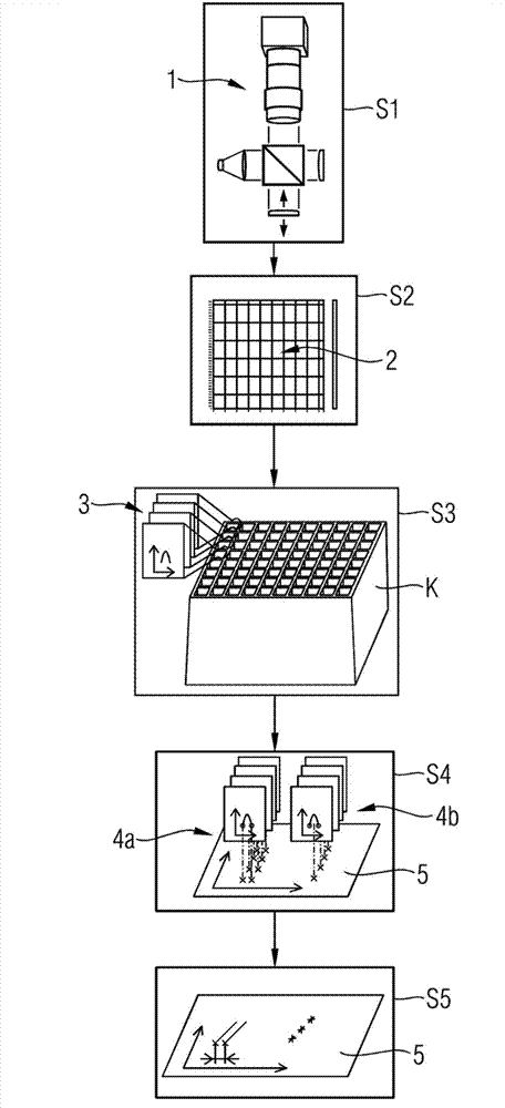
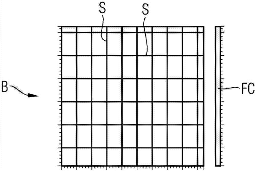
[0036] figure 1 A schematic diagram of a method sequence according to the invention with method steps S1 to S5 is shown. This method is carried out in order to check the dimensional accuracy of the edges of the collimator K. The collimator K is a two-dimensional scattering shielding grid with a plurality of rectangular mutually arranged tubes, the walls of which form a grid sheet with edges and grid holes. The collimator K has an entry plane and an exit plane for the radiation to be attenuated, the entry plane being smaller than the exit plane. In the configuration shown here, the entry plane of the collimator K is checked.

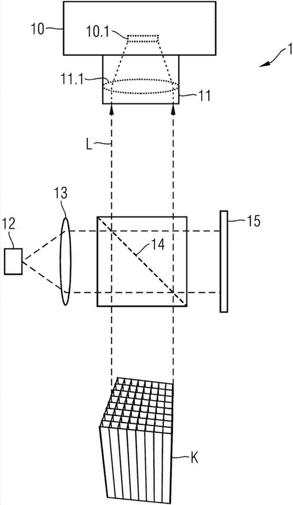
[0037] To do this, perform the steps described below. In a first step S1 , a three-dimensional measurement data record 2 of the collimator K is generated by the white light interferometer 1 and output in a step S2 . The measurement data set 2 contains in particular three-dimensional height information about the slices of the collimator. In a method ste...


PUM


Abstract

The present invention relates to a method and a device for the production and detection of a collimator, in particular for the edge detection of a collimator (K). The method involves generating (S1) at least one three-dimensional measurement data set (2) of the collimator (K); determining (S2) a plurality of transverse profile data (3) of webs of the collimator on the at least one measuring data set (2); evaluating (S3) the transverse profile characteristics (4a,4b) of the transverse profile data; generating (S4) at least one two-dimensional projection data set (5) by projecting the transverse profile characteristics of the transverse profile data; and evaluating (S5) the at least one two-dimensional projection data set (5). The preset invention also relates to a device for executing the method for the production and detection of a collimator (K), thereby performing the production and detection of the collimator (K) through the device for executing the method.

Description

technical field [0001] The invention relates to a method and a device for the production inspection of collimators. Background technique [0002] Collimators for scatter attenuation in CT systems are generally known. In both clinical and technical applications of CT systems, larger systems are constantly being used with larger detectors, particularly greater detector depths in the scan direction. Here, increased scatter occurs, so that scatter suppression and scatter attenuation become increasingly important. An effective suppression of scattering requires collimators which can attenuate the scattering in multiple directions, for example in the form of a two-dimensional scattering shielding grid. Such grid-shaped collimators are formed, for example, by side-by-side arrays of thin-walled tubes with circular, rectangular or hexagonal cross-sections. The tubes or grid sheets are, for example, designed with a conical cross-section or a frusto-conical shape, wherein the walls ...

Claims


Application Information

Patent Timeline
Patent Type & Authority Applications(China)
IPC IPC(8): G01B11/02G01B11/14G01B11/24
CPCG01B11/028G01B11/2441G21K1/025
Inventor M.米斯S.沃思J.雷格
Owner SIEMENS AG
Why Eureka
Try Eureka