Measuring device for two-phase flow split-phase flow in steady state

A measurement device and phase flow technology, applied in the direction of volume flow measurement device, measurement device, liquid/fluid solid measurement, etc. problems, to achieve the effect of increasing the repeated service life, simplifying the processing technology, and convenient operation.

Active Publication Date: 2016-03-30
XI AN JIAOTONG UNIV
View PDF8 Cites 0 Cited by
  • Summary
  • Abstract
  • Description
  • Claims
  • Application Information

AI Technical Summary

Problems solved by technology

However, this method uses gravity for steam-water separation, which is more suitable for air-water separation of two-phase flow in the case of stratified flow. For other forms of flow, such as slug flow, bubbly flow and other gas-liquid mixing together, there is no obvious difference. , Two-phase flow with a clear interface, the effect of gravity separation alone is not good, the gas phase will entrain the liquid phase and enter the gas outlet on the upper part of the container, resulting in deviations in the measurement of the phase-separated flow
Moreover, this method does not have any thermal insulation or heat dissipation compensation measures. Due to the influence of steam condensation, the phase-separated flow measurement of steam-water two-phase flow cannot be carried out, so this device is not suitable for two-phase flow of other flow types other than stratified flow. flow, and is not suitable for phase-separated flow measurement of steam-water two-phase flow
In addition, the above method does not take into account how to maintain a stable pressure in the large container, and is only suitable for phase-separated flow measurement at lower pressures

Method used


Image

  • Measuring device for two-phase flow split-phase flow in steady state
  • Measuring device for two-phase flow split-phase flow in steady state
  • Measuring device for two-phase flow split-phase flow in steady state

Examples


Embodiment Construction

[0031] The technical scheme of the present invention will be described in detail below in conjunction with the accompanying drawings.

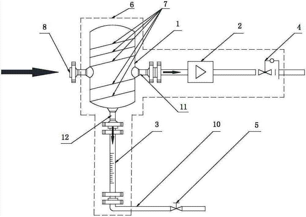
[0032] like figure 1 As shown, the device for measuring the flow rate of the two-phase flow in the steady state of the present invention mainly includes: a steam-water separator 1, a gas flow meter 2, a quartz glass tube with scale 3, a pressure reducing valve 4 and a shut-off valve 5.

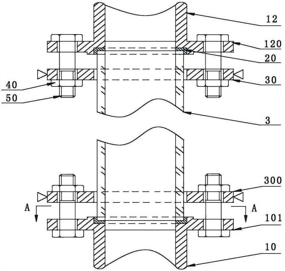
[0033] The side wall of the steam-water separator 1 is horizontally provided with a two-phase flow inlet 8 and a first outlet, and the bottom wall of the steam-water separator 1 is vertically provided with a second outlet. The vertically arranged second outlet is the liquid outlet after the separation of the two-phase flow, and the horizontally arranged first outlet is the gas / vapour outlet, which is connected with a metal pipe 11 . The second outlet is connected with a first metal tube 12, the first metal tube 12 is sealingly connected with the quartz glass ...


PUM


Abstract

The invention discloses a device for measuring a split-phase flow of a two-phase flow under a steady state condition. The device mainly comprises a steam-water separator, a gas flow meter, a quartz glass tube, a pressure reducing valve and a stop valve. A two-phase flow inlet and a first outlet are horizontally formed in the sidewall of the steam-water separator. A second outlet is vertically formed in the bottom wall of the steam-water separator. The vertically formed second outlet is a two-phase flow separated liquid outlet. The horizontally formed first outlet is a gas / steam outlet. The second outlet is connected with a first metal tube which is in sealed connection with the quartz glass tube with scales. The lower part of the quartz glass tube is in sealed connection with a second metal tube with the stop valve. The first outlet is in sealed connection with a metal pipeline with the gas flow meter and the pressure reducing valve through a flange. Requirements on the measurement of the split-phase flow of an air-water or steam-saturated water two-phase flow are met, and the device can work safely and reliably, and is rational in design, compact in structure, easy to operate, applicable to the measurement of the split-phase flow of the two-phase flow under a high pressure condition and particularly suitable for the measurement of a high-gas content two-phase flow.

Description

technical field [0001] The invention belongs to the technical field of fluid measurement, and in particular relates to a measuring device for two-phase flow split-phase flow in a steady state. Background technique [0002] Vapor / gas-liquid two-phase flow widely exists in energy, chemical and other fields. The measurement of parameters such as phase separation flow in two-phase flow can be mainly divided into two categories: non-traditional measurement means and traditional measurement means. Non-traditional measurement methods often use new technology for measurement. This method has the characteristics of real-time and rapidity, but such devices are often complex, expensive, demanding in terms of use, and demanding on the measurement site. Sex is controversial, for example, with rays, probes, etc. However, the traditional method and device combined with a single-phase flow instrument to measure two-phase parameters has the advantages of mature technology, low cost, simple...

Claims


Application Information

Patent Timeline
Patent Type & Authority Patents(China)
IPC IPC(8): G01F7/00G01F11/28G01F1/32
Inventor 苏光辉孟兆明田文喜秋穗正巫英伟王来顺
Owner XI AN JIAOTONG UNIV
Why Eureka
Try Eureka