System capable of automatically compensating and focusing in process of automatic scanning and method and application thereof

An automatic compensation and automatic scanning technology, applied in microscopes, optics, instruments, etc., can solve problems such as unsatisfactory actual results and affect image clarity, and achieve the effect of not easy to slide down, light weight, and easy to control.

Active Publication Date: 2013-04-10
MOTIC CHINA GRP CO LTD
View PDF4 Cites 9 Cited by
  • Summary
  • Abstract
  • Description
  • Claims
  • Application Information

AI Technical Summary

Problems solved by technology

When the actual stage moves X and Y, errors will occur due to mechanical processing and assembly errors, which will cause micron-level fluctuation errors on the surface of the stage. As long as this fluctuation exceeds the depth of field of the objective lens, it will affect

Method used


Image

  • System capable of automatically compensating and focusing in process of automatic scanning and method and application thereof
  • System capable of automatically compensating and focusing in process of automatic scanning and method and application thereof
  • System capable of automatically compensating and focusing in process of automatic scanning and method and application thereof

Examples


Embodiment

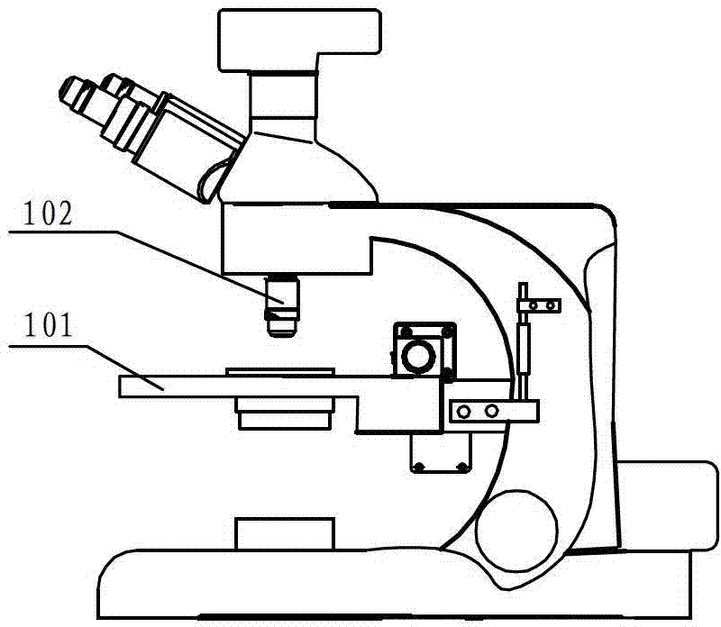
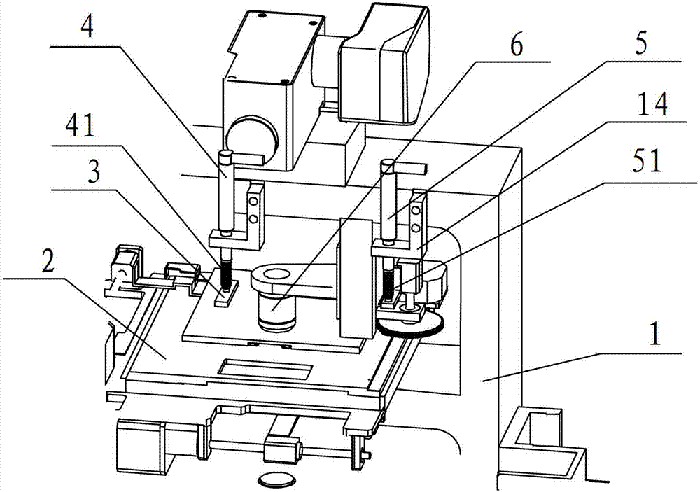
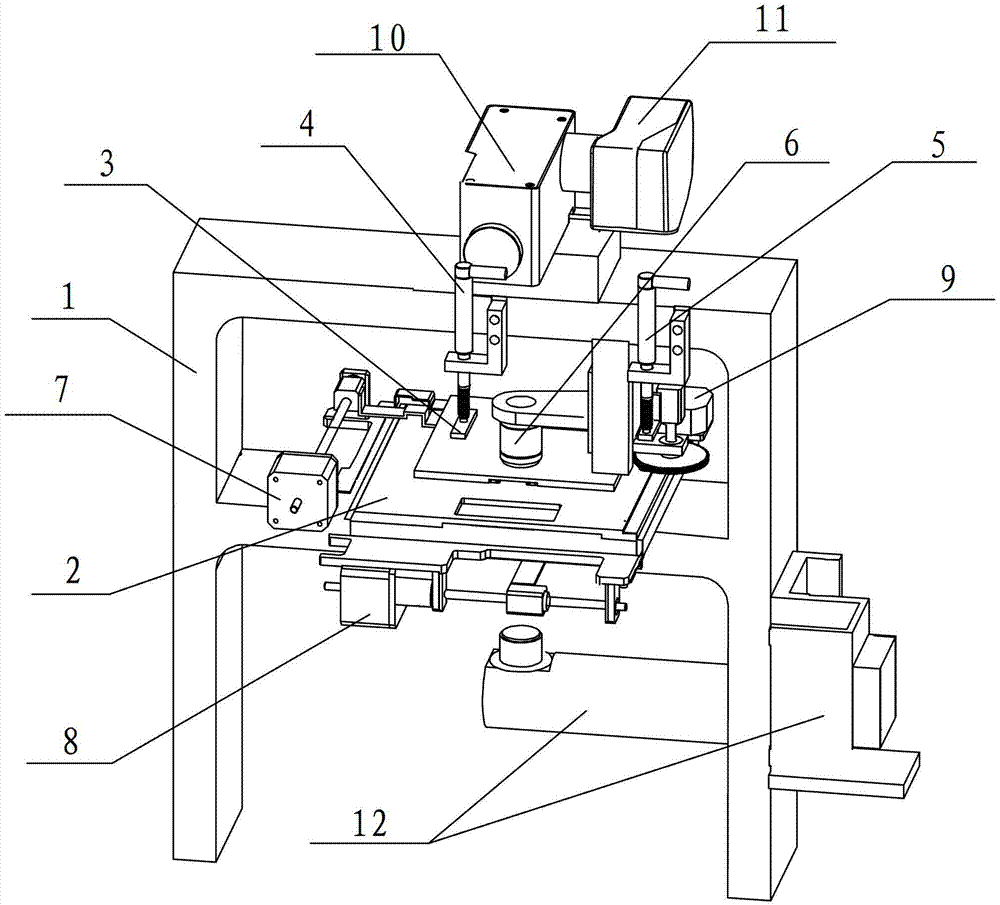
[0051] Such as image 3 , Figure 4 , Figure 5 A microscope based on a system for automatically compensating focus during automatic scanning is shown, including: a frame 1, an objective lens, a motor-driven stage, a motor-driven focusing (Z-axis) mechanism, an imaging optical system 10, Digital camera 11, light source lighting system 12.

[0052] The frame 1 is a gantry structure, and the object stage is fixed on the gantry frame. The object stage can move in the X and Y directions, but remains stationary in the Z direction, and is always fixed on the gantry frame. The gantry has enough rigidity to support the four corners of the stage to ensure that the change of the center of gravity of the stage caused by the movement of the stage in the X and Y directions will not affect the Z direction.

[0053] The stage is driven by motors, the first motor 7 drives the stage to move in the X direction, and the second motor 8 drives the stage to move in the Y direction.

[0054] The...


PUM


Abstract

The invention relates to a system capable of automatically compensating and focusing in a process of automatic scanning, an implementation method thereof and an application thereof on a microscope, and is used for compensating and revising tiny errors caused by factors such as mechanical motions, machining work and installations, and expansions caused by heat and contractions caused by cold, so that the microscope is guaranteed to gain a clear image on each view field in the process of scanning. The system capable of automatically compensating and focusing comprises a target platform and an imaging device. The target platform moves in a plane. The imaging device moves in a direction perpendicular to the target platform. The system capable of automatically compensating and focusing further comprises a focusing and compensating system which comprises at least two displacement measuring devices. The first displacement measuring device is installed on the target platform and is used for detecting displacement errors in the vertical direction in the movement process of the target platform. The second displacement measuring device is installed on the imaging device and is used for detecting a relative distance between a lens of the imaging device and the target platform.

Description

technical field [0001] The present invention relates to a compensating focusing system, more specifically, to a system for automatically compensating focusing during automatic scanning, and a method for realizing it, which is applied to a microscope to correct Small errors caused by factors such as installation, thermal expansion and contraction are compensated and corrected, so as to ensure that each field of view can obtain a clear image during the scanning process of the microscope. Background technique [0002] The automatic microscope scanning system is a high-precision scanning instrument that has appeared in recent years, and is widely used in medical research, clinical application, biological research and industrial application. Conventional microscope scanning systems such as figure 1 As shown, the objective lens 102 remains stationary during focusing, and the stage 101 drives the measured object to move up and down. There is also a sensor that uses a sensor to de...

Claims


Application Information

Patent Timeline
IPC IPC(8): G02B21/24G02B21/36
Inventor 康军高志刚
Owner MOTIC CHINA GRP CO LTD
Why Eureka
Try Eureka