Special vehicle signal priority control method based on global position system (GPS)

A signal priority, special vehicle technology, applied in the traffic control system of road vehicles, traffic control systems, instruments, etc., can solve the problems of priority control, priority signal signal priority control effect, etc., to improve efficiency and simplify equipment maintenance in the later stage , The effect of reducing construction costs

Inactive Publication Date: 2013-04-10
JIANGSU ZHITONG TRANSPORTATION TECH +1
4 Cites 20 Cited by

AI-Extracted Technical Summary

Problems solved by technology

[0009] In view of the fact that the existing traditional special vehicle signal priority control method cannot provide a suitable priority signal timing and the timing of restoring the intersection signal phase sequence, the signal priority control effect is too low. For th...

Abstract

The invention discloses a special vehicle signal priority control method based on a global position system (GPS). The special vehicle signal priority control method is a data processing method which bases on signal prior route configuration information and real-time GPS data, utilizes the geographic information system (GIS) technology, automatically identifies signalized intersections which need executing a signal priority control scheme through an electric fence, automatically identifies signalized intersections which need recovering a normal signal control scheme through road segment map matching and an unlocking delayer, and takes multiple signal prior tasks into consider at the same time. The special vehicle signal priority control method can flexibly provide an autonomous and intelligentized signal prior service for various special vehicles, and has a positive meaning in improving the signal prior service level for the special vehicles and achieving informatization and intelligence of urban traffic management.

Application Domain

Technology Topic

Image

  • Special vehicle signal priority control method based on global position system (GPS)
  • Special vehicle signal priority control method based on global position system (GPS)
  • Special vehicle signal priority control method based on global position system (GPS)

Examples

  • Experimental program(1)

Example Embodiment

[0060] In the following, the present invention will be further clarified with reference to specific examples. It should be understood that these examples are only used to illustrate the present invention and not to limit the scope of the present invention. After reading the present invention, those skilled in the art will understand various equivalent forms of the present invention. All the modifications fall within the scope defined by the appended claims of this application.
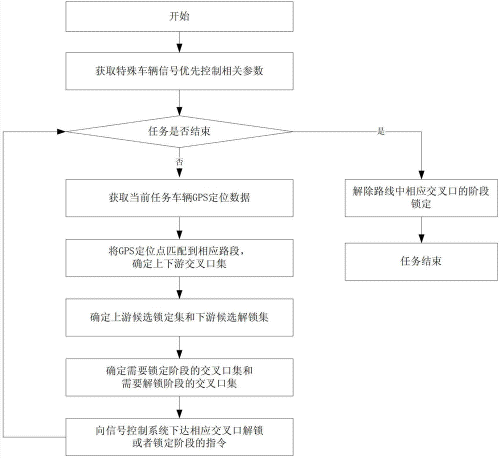
[0061] Such as figure 1 Shown is the flow chart of GPS-based special vehicle signal priority control method. The specific implementation steps are as follows:
[0062] 1) Obtain the configuration parameters of special vehicle signal priority control tasks in real time, and construct the signal priority information table of priority route intersections;
[0063] Special vehicle signal priority control task configuration parameters, mainly including priority route, priority level, number of vehicles included in the fleet, and priority phase; intersection signal priority information table is used to temporarily store information about signal priority tasks and unlock delay timers. If the table is empty, it means that the intersection is not in the phase lock state, if it is not empty, it means that the intersection is in the phase lock state by one or more priority tasks at the same time.
[0064] 2) Determine whether the task is over, that is, whether the user sends the task end instruction after the task is over or during the execution of the task, if not, go to step 3), otherwise go to step 8).
[0065] 3) Real-time acquisition of GPS data of special vehicles on the current mission.
[0066] 4) Combine electronic map data, such as Figure 4 As shown, matching the GPS positioning point to the corresponding road section, and using the road section as a benchmark, divides the downstream intersection set and upstream intersection set of the priority route, including the following steps:
[0067] a) Take the centerline of each section of the priority route as a reference as a buffer zone, whose range is the sum of the section width and the GPS positioning error;
[0068] b) Select the road segment corresponding to the buffer zone containing the GPS positioning point as the primary matching road segment;
[0069] c) If the matching road section is unique in the primary selection, it means that the road section is the matching road section of the GPS positioning point, and the vertical projection point is the vehicle position matching point. If it is not unique, it means that the vehicle has not completely passed through the intersection. The upstream section is used as the matching section of the GPS positioning point, and the end of the matching section is the vehicle position matching point.
[0070] 5) Determine the downstream candidate phase locked intersection set and upstream candidate unlocked intersection set:
[0071] 5-1) Based on the electronic fence of the downstream intersection set, determining the downstream candidate phase locked intersection set includes the following steps:
[0072] a) Determine the radiation radius of the electronic fence according to the priority of the task;
[0073] b) Generate electronic fence based on the downstream intersection set;
[0074] c) Select the intersection corresponding to the electronic fence containing GPS positioning points as the candidate phase locked intersection set;
[0075] 5-2) Take the upstream intersection set as the upstream candidate unlocked intersection set.
[0076] 6) Determine the intersection set that needs to be locked and the intersection set that needs to be unlocked in the phase:
[0077] 6-1) According to the signal priority information table of the locked intersection set in the downstream candidate stage, determine the intersection set in the locked stage, such as figure 2 As shown, including the following steps:
[0078] a) If the signal priority information table of a locked intersection in the candidate phase is empty, it means that the intersection is in an unlocked state, add current task-related information to the table, and add the intersection to the intersection set of the locked phase. Go to step d), otherwise, go to step b);
[0079] b) If the signal priority information table does not contain the current task information, then determine whether the current task lock phase is the same as other task lock phases. If yes, it means that the current task can obtain signal priority access rights at the same time as other tasks, and add current task related information To this table, go to step d), otherwise, go to step c);
[0080] c) If the priority level of the current task is greater than the priority level of other tasks in the table, judge whether the distance between other task priority vehicles and the current intersection is greater than or equal to the safe stopping distance, if it is, it means that the intersection phase lock can be switched, giving high priority Priority right of passage for special vehicle signals, clear the signal priority information table, add current task-related information to the table, and add the intersection to the intersection set that needs to be locked, go to step d), otherwise, go to step d);
[0081] d) Repeat steps a) to c) to process each intersection in the locked intersection set in the candidate phase, that is, the intersection set in the locked phase is obtained;
[0082] 6-2) According to the signal priority information table of the upstream candidate unlocked intersection set, determine the intersection set that needs to be unlocked in the phase, such as image 3 As shown, including the following steps:
[0083] a) Determine that the signal priority information table of the candidate unlocked intersection contains the current task, then go to step b), otherwise go to step e);
[0084] b) If the task contained in the signal priority information table is unique, it means that the intersection is only locked by the current task, go to step c), otherwise, go to step d);
[0085] c) Determine whether the unlock delay timer time is greater than or equal to the fleet passing time. If it is, it means that the fleet has completely passed the intersection, clear the signal priority information table, and add the intersection to the intersection set that needs to be unlocked during the phase, and then transfer to Step e), otherwise, go to step e);
[0086] d) Remove the current task information from the signal priority information table and proceed to step e);
[0087] e) Repeat steps a) to d) to process each intersection in the candidate unlocked intersection set, that is, the intersection set that needs to be unlocked in the phase.
[0088] 7) According to the set of intersections that need to be locked and the set of intersections that need to be unlocked, the signal control system will issue instructions for locking and unlocking the corresponding intersections.
[0089] 8) According to the signal priority information table of the priority route intersection, release the phase lock of the corresponding intersection on the task route, including the following steps:
[0090] a) If the signal priority information table of the priority route intersection contains the current task and is unique, then add the intersection to the intersection set that needs to be unlocked, and go to step c), otherwise go to step b);
[0091] b) If the signal priority information table contains the current task, remove the current task information in the table and go to step c), otherwise go to step 3);
[0092] c) Repeat steps a) to b) to process each intersection included in the priority route, that is, the set of intersections that need to be unlocked in the phase;
[0093] d) According to the set of intersections that need to be unlocked, unlock the corresponding intersection on the mission route; then end the current mission.

PUM

no PUM

Description & Claims & Application Information

We can also present the details of the Description, Claims and Application information to help users get a comprehensive understanding of the technical details of the patent, such as background art, summary of invention, brief description of drawings, description of embodiments, and other original content. On the other hand, users can also determine the specific scope of protection of the technology through the list of claims; as well as understand the changes in the life cycle of the technology with the presentation of the patent timeline. Login to view more.

Similar technology patents

Computer-controlled expansion accumulative lifting method for erecting super-high arch grid structure

ActiveCN104947942AReduce construction costsThe construction period is highly controllableArched structuresVaulted structuresEngineeringComputational analysis
Owner:浙江东南网架股份有限公司

Classification and recommendation of technical efficacy words

Why Eureka
Try Eureka