
Directional migration method and directional migration device

A technology of directional migration and equipment, applied in the direction of electrical components, wireless communication, etc., can solve the problems of increasing network resource overhead, poor user perception, occupying large network resources and routing data, etc., to reduce call waiting time and improve user Sensitivity, cost-saving effect

Active Publication Date: 2016-01-20
XINYANG BRANCH HENAN CO LTD OF CHINA MOBILE COMM CORP
View PDF3 Cites 0 Cited by
  • Summary
  • Abstract
  • Description
  • Claims
  • Application Information

AI Technical Summary

Problems solved by technology

[0005] Since the NNSF in the MSCPool technology assigns MSCs to terminals that access for the first time, it follows the principle of MSC load balancing, so terminals under the same BSC may be evenly allocated to different MSCs, because terminals under the same BSC are geographically close , may be located in the same place (for example: offices, places where residential areas are concentrated, etc.), therefore, when terminals under the same BSC are assigned to different MSCs, the calls between terminals under the same BSC are inter-office calls between different MSCs , a large number of inter-office calls will occupy a large amount of network resources and routing data, increase the overhead of network resources, and may also cause problems such as increased call connection delay and connection error rate, making user perception poor

Method used


Image

  • Directional migration method and directional migration device
  • Directional migration method and directional migration device
  • Directional migration method and directional migration device

Examples


Embodiment 1

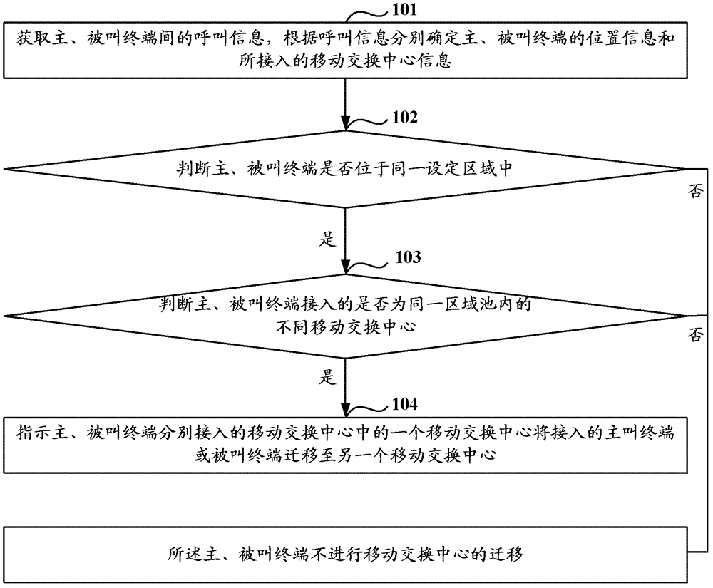
[0023] like figure 1 As shown, it is a flowchart of a method for directional migration in the first embodiment. The implementation of the first embodiment includes the following steps:

[0024] Step 101: Obtain call information between the calling terminal and the called terminal, and respectively determine the location information of the calling terminal and the called terminal and the information of the mobile switching center they are connected to according to the call information.

[0025] Step 102: According to the location information of the calling terminal and the called terminal, judge whether the calling terminal and the called terminal are located in the same setting area, if so, then perform step 103, otherwise, the calling and called terminals do not perform the migration of the mobile switching center .

[0026] In the scheme of this embodiment, the situation that the calling terminal and the called terminal are located in the same location area code LAC can be...

Embodiment 2

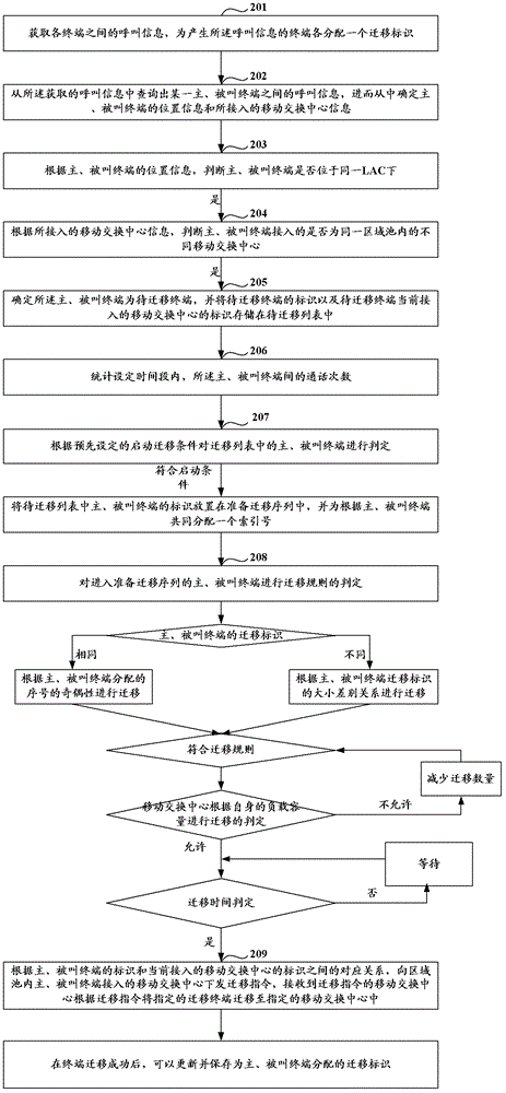
[0034] like figure 2 As shown, it is a flowchart of a method for directional migration in the second embodiment. The second embodiment is a detailed description of the specific implementation of each step in the first embodiment, and the solution of the second embodiment includes the following steps:

[0035] Step 201: Obtain call information between terminals, and assign a migration identifier to each terminal generating the call information.

[0036]It should be noted that in the structure of the MSCPool network, the call information between terminals can be read from the database of other call record real-time statistics systems (such as: signaling monitoring system, bill collection system, etc.), or it can be Call information between terminals collected and stored locally.

[0037] Preferably, the acquired call information may be inter-office call information between terminals connected to different mobile switching centers.

[0038] The call information includes: the ...

Embodiment 3

[0074] Embodiment 3 of the present invention provides a device for converting an inter-office call into an intra-office call under the same inventive concept as Embodiment 1 and Embodiment 2, such as image 3 As shown, it is a schematic structural diagram of a directional migration device in the third embodiment. The directional migration device includes: an information storage module 11 , a statistical analysis module 12 and a directional migration module 13 .

[0075] Specifically, the information storage module 11 is used to store the location information of the calling and called terminals and the information of the connected mobile switching center; the statistical analysis module 12 is used to judge the location information of the calling and called terminals according to the location information Whether it is located in the same setting area, and according to the information of the mobile switching center accessed, it is judged whether the calling terminal and the calle...


PUM


Abstract

The invention discloses a method and a device of directed migration. The method of the directed migration comprises confirming the position information of a calling terminal and a called terminal and accessed mobile switching center information according to calling information between the calling terminal and the called terminal, confirming that the calling terminal and the called terminal are in an identical set area according to the position information of the calling terminal and the called terminal, and indicating one mobile switching center of the mobile switching centers respectively accessed by the calling terminal and the called terminals to move the calling terminal or the called terminal to another mobile switching center when the calling terminal and the called terminal are confirmed to access different mobile switching centers of one identical area according to the accessed mobile switching center information. In other words, station to station call between the calling terminal and the called terminal with close positions are converted to office call, and therefore the quantity of the station to station call in a network is reduced, the overhead of network resources is reduced, and the perceptibility of a user is improved.

Description

technical field [0001] The invention relates to the field of wireless communication, in particular to a method for directional migration and a device for directional migration. Background technique [0002] In 1999, 3GPP (The3rdGenerationPartnershipProject, third-generation partnership project) proposed the MSCPool (MobileSwitchingCenterPool, mobile switching center pool) technology. Compared with the traditional networking method, the MSCPool technology introduced the concept of "pool area" (PoolArea): An MSC regional pool is composed of multiple mobile switching centers (including MSC (Mobile Switching Center) or MSS (Mobile Switching Center Server)), and one BSC / RNC (Base Station Controller / Radio Network Controller, base station controller / radio network controller) can be connected to multiple a mobile switching center. After a terminal (MS or UE) accesses a BSC / RNC, the BSC / RNC can register the terminal with any mobile switching center connected to the BSC / RNC. [0003...

Claims


Application Information

Patent Timeline
Patent Type & Authority Patents(China)
IPC IPC(8): H04W36/12
Inventor 刘遂江宋亚丽周忠良
Owner XINYANG BRANCH HENAN CO LTD OF CHINA MOBILE COMM CORP
Learn More