Injector

A technology for syringes and syringes, applied in the field of disposable syringes, can solve problems such as operational errors, and achieve the effects of safety assurance, convenient operation, and improved hand feeling

Inactive Publication Date: 2013-04-17
SUZHOU YASI PRECISION MOLD
View PDF4 Cites 2 Cited by
  • Summary
  • Abstract
  • Description
  • Claims
  • Application Information

AI Technical Summary

Problems solved by technology

[0007] However, since the injection is completed when the push rod is pushed to the bottom, that is, the fixed-stroke piston is on the brake ring, at this time, it only needs to push a little harder, and it will be activated immediately The brake ring unloads the force of the Luer cone and separates from the limit structure on the syringe. The syringe can no longer be used. However, when the medical staff uses the syringe, it also needs to be pushed. The push rod, which makes the medical staff dare not push the needle, so as not to trigger the brake ring to unload force when pushed to the end, and the medical staff is used to push the push rod to the end, which is due to the long-term use of ordinary syringes to develop needle push Therefore, the use of the current safety syringe does not match the routine use of medical staff, which leads to errors in operation, and further improvement is needed

Method used


Image

  • Injector
  • Injector
  • Injector

Examples


Embodiment 1

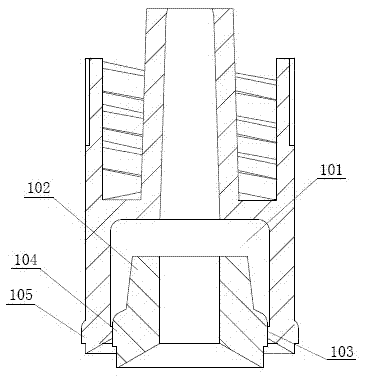
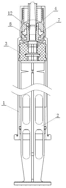
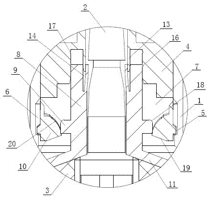
[0032] Embodiment one: see Figure 2-6 As shown, a syringe includes a syringe 1, a push rod 2 and a needle. The push rod 2 is arranged in the syringe 1. The front end of the push rod 2 is covered with a sealing rubber plug 3. The needle is passed through a Luer cone. The head 4 is arranged on the front end of the syringe 1, the outer edge of the luer head 4 is provided with a limiting rib 5, and the inner wall of the syringe 1 is provided with a limiting groove 6 cooperating with the limiting rib 5. The rear end of the Luer cone 4 is provided with an unloading chamber 7, and a unloading sealing sleeve 8 is arranged in the unloading chamber 7, and the unloading sealing sleeve 8 is provided with expansion ribs 9, and the Luer cone 4 is unloaded. In the force chamber 7, a protrusion 10 is provided corresponding to the limiting rib 5 to cooperate with the expansion rib 9, and the bottom of the force relief sealing sleeve 8 is provided with a tapered surface structure 11 to coope...


PUM


Abstract

The invention discloses an injector comprising a syringe, a push rod and a syringe needle. The push rod is arranged in the syringe, a sealing rubber plug is sleeved at the front end of the push rod, and the syringe needle is arranged at the front end of the syringe through a Ruehl cone. The injector is characterized in that a conical surface structure matched with the top end of the sealing rubber plug is arranged at the bottom of an unloading sealing sleeve, the outer edge of the conical surface structure and the inner wall of the syringe form a hydraulic seal, and an interval section in 1-2mm is arranged between the conical surface structure and an expansion rib, so that a null-traveling stroke is obtained between the upper surface of the conical structure and the inner wall of the syringe, an elastic lock catch is arranged at the top end of the unloading sealing device, a fastening ring matched with the elastic lock catch in a socket manner is arranged in an unloading cavity, and pushing force of the unloading sealing sleeve moving along the null-traveling stroke is at least twice times of that for injecting medical liquid. By the aid of the null-traveling stroke and the elastic lock catch, pushing force triggering unloading is increased, false triggering of the Ruehl cone is avoided, and conventional using habits are complied.

Description

[0001] technical field [0002] The invention relates to a medical device, in particular to a disposable syringe. [0003] Background technique [0004] With the increasing development of the medical industry, the hygienic requirements for medical devices are getting higher and higher. Syringes account for a large part of medical devices. In order to avoid cross-infection when inputting or removing media for humans or animals, disposable syringes As a conventional medical device, it has been widely used in the modern medical industry, and it is disposed of as medical waste after use. [0005] At present, the mainstream syringes on the market are divided into two types: ordinary type and safety type. The ordinary type is usually composed of a syringe, a push rod, a fixed stroke piston and a needle. The end of the syringe is provided with a connector for inserting the needle. On the connector, the fixed-stroke piston is sleeved on the front end of the push rod. The push rod ...

Claims


Application Information

Patent Timeline
Patent Type & Authority Applications(China)
IPC IPC(8): A61M5/178A61M5/31
Inventor 胡文忠
Owner SUZHOU YASI PRECISION MOLD
Why Eureka
Try Eureka