Automatic edge cutting method for plant fiber molding product and automatic edge cutting machine

A technology of molded products and plant fibers, applied in the field of automatic trimming equipment, can solve problems such as unhygienic, unsafe, and travel restrictions in up and down movements

Active Publication Date: 2013-04-17
EURASIA EP MACHINERY +1
View PDF5 Cites 9 Cited by
  • Summary
  • Abstract
  • Description
  • Claims
  • Application Information

AI Technical Summary

Problems solved by technology

[0004] The disadvantages of the above methods are: low efficiency and unsafe, unhygienic
Using this method to make the suction cup move up and down, its up and down movement stroke is greatly restricted and the horizontal impact force is relatively large.
[0012] Looking at all the tri

Method used


Image

  • Automatic edge cutting method for plant fiber molding product and automatic edge cutting machine
  • Automatic edge cutting method for plant fiber molding product and automatic edge cutting machine
  • Automatic edge cutting method for plant fiber molding product and automatic edge cutting machine

Examples


Embodiment 1

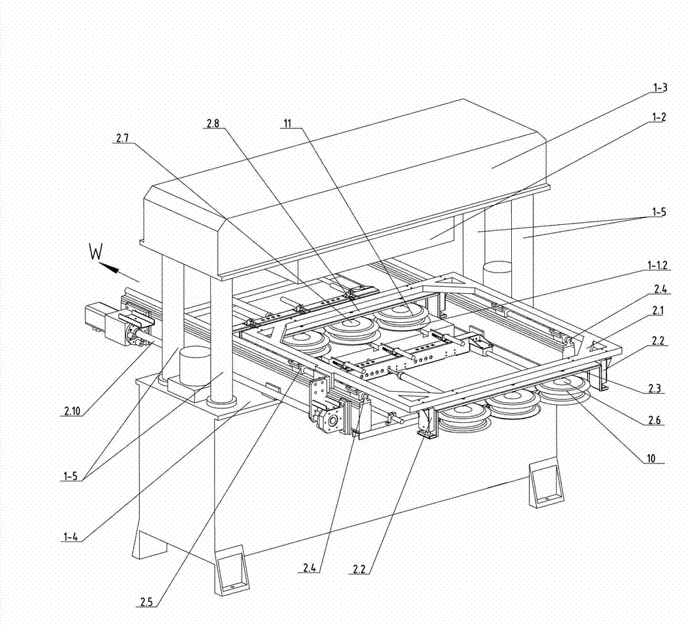
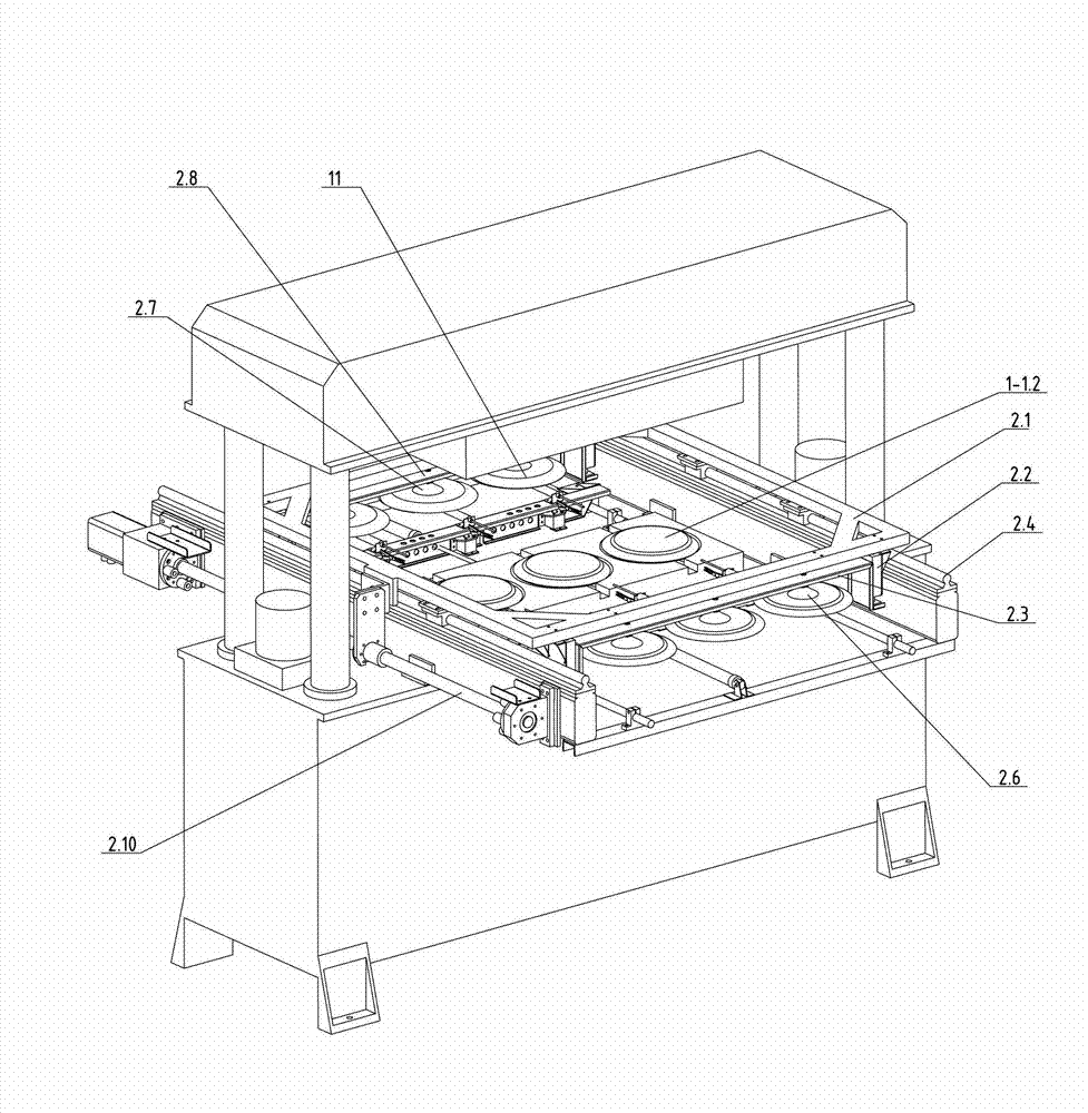
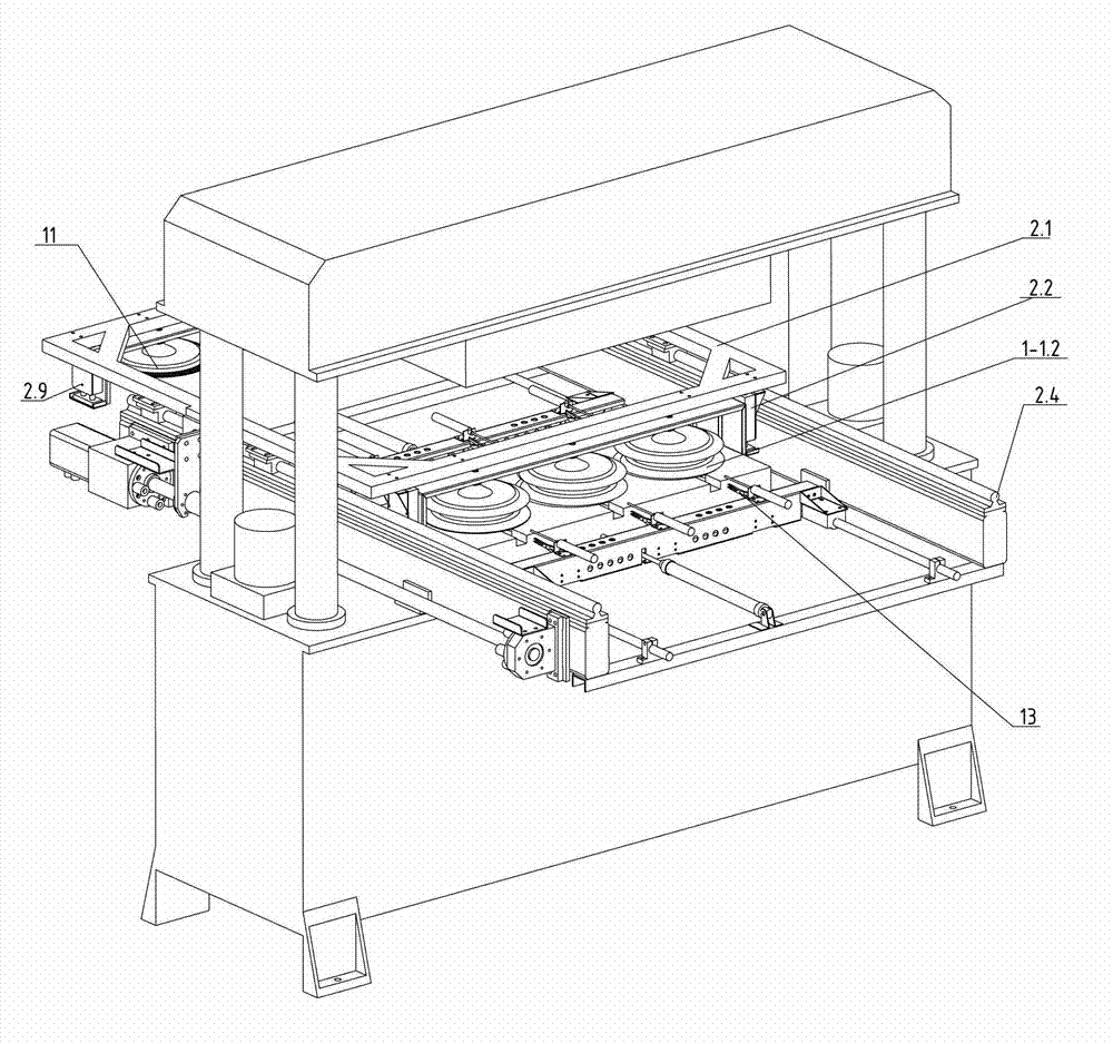
[0077] Such as image 3 , Figure 4 , Figure 5 , Figure 12-1 , Figure 13 The automatic edge trimming machine for plant fiber molded products shown includes: an edge trimming and clamping mechanism, a product transfer mechanism, and a waste edge removal mechanism. The trimming and clamping mechanism mainly includes an upper trimming mold; an upper mounting plate, a lower trimming mold, a lower mounting plate, and a power mechanism. The power mechanism directly or indirectly drives the upper mounting plate to move relative to the lower mounting plate. The trimming and clamping mechanism can have various forms, such as: three-plate type trimming and clamping mechanism ( Figure 11 shown) and two-plate type trimming and clamping mechanism ( Figure 9 shown).

[0078] The two-plate type trimming and mold clamping mechanism includes: upper trimming mold, upper mounting plate, lower trimming mold, lower mounting plate, clamping rod, drive (including direct drive or indirect...

Embodiment 2

[0108] Such as Figure 15 , Figure 16 As shown, in the automatic trimming machine for plant fiber molded products described in this embodiment, the specific structure of its product transfer mechanism can also be a rod-type product transfer mechanism.

[0109] The transport frame in Embodiment 1 is a transport bar 15 in this embodiment, and the transport bar is not a frame structure but a bar, which can also be called a bar type transport frame. Root bar is called delivery bar, and the disk opening of front row suction cup group 2.6 is fixed on the front fixed plate 2.3 downwards, and the disk mouth of rear row suction cup group 2.7 is fixed on the rear fixed plate 2.8 downwards, and one end of the front fixed plate and the rear One end of the fixed plate is installed on the conveying rod at a certain interval, and generally there is a space greater than the contour of the upper trimming mold between the front and back two rows of suction cup groups. The two ends of the del...


PUM


Abstract

The invention relates to an automatic edge cutting method for a plant fiber molding product and an automatic edge cutting machine. The purposes are that the method has the characteristic of automatic and accurate location, and the automatic cutting machine has the characteristic of stable work. The technical scheme includes that the automatic edge cutting method for the plant fiber molding product proceeds as follows: 1), sucking the product with edges to be cut; 2), driving away waste edges from an edge cutting position; 3), positioning the product to be cut and a product with cut edges respectively; 4), cutting out deckle edges; 5), enabling a front row and a rear row of sucking disk sets to reach the corresponding positions respectively; and 6), sucking the product with edges to be cut and the product with cut edges; repeating from the step 2) to the step 6), and proceeding the circulation over and over again. The automatic edge cutting machine for the plant fiber molding product comprises an edge cutting and die assembly mechanism, wherein the edge cutting and die assembly mechanism comprises an upper edge cutting mold, a lower edge cutting mold, an upper installation plate, a lower installation plate and a power mechanism. The automatic edge cutting machine for the plant fiber molding product is characterized in that a product transferring mechanism and a waste edge moving out mechanism are also arranged on the automatic edge cutting machine.

Description

technical field [0001] The present invention relates to an automatic edge trimming method and an automatic edge trimmer for plant fiber (referred to as plant fiber; hereinafter the same) molded products and plastic thin products including pulp; especially the redundant edges of plant fiber molded products and plastic thin products Automatic cutting and automatic cutting methods, automatic cutting methods for single products in conjoined products (hereinafter collectively referred to as trimming), and corresponding automatic trimming equipment. Background technique [0002] Existing plant fiber molding production equipment, the actual edge of the plant fiber molded product produced often does not meet the design requirements; for example, the outer edge of the same product, some parts are larger than the design edge of the product and some parts are smaller than the design of the product Edges, or edges with small burrs and other undesirable phenomena. In order to achieve a ...

Claims


Application Information

Patent Timeline
IPC IPC(8): B29C37/02B26D7/06B26D7/01B26D7/18B26D7/32
Inventor 李瑾菁郑天波王建新求亚珍丁士琴郑俭学郑晓香何益峰洪锡平郑卓
Owner EURASIA EP MACHINERY
Why Eureka
Try Eureka