Method and device for replacing wheel group of bridge crane

An overhead crane and wheel set technology, applied in the field of machinery, can solve the problems of the wheel set and the balance beam assembly being large in weight and dimensions, endangering the safety of operators, difficult in actual operation, etc., so as to prevent personal injury accidents and simplify operation steps. , the effect of reducing the intensity and complexity of the work

Active Publication Date: 2015-03-11
ANSHAN IRON & STEEL GROUP CORPORATION
View PDF5 Cites 1 Cited by
  • Summary
  • Abstract
  • Description
  • Claims
  • Application Information

AI Technical Summary

Problems solved by technology

[0002] The wheel set and balance beam assembly of a large-tonnage bridge crane in a steelmaking plant have a large weight and overall size. Taking a 300t crane as an example, the traveling wheel set weighs about 13t, is 6.3m long, and 1.8m high. When replacing the wheel set, in order to maintain The usual way to balance the wheel set is to hang multiple chain cranes within a small angle range above the wheel set. The operator operates on the side of the wheel set. When the wheel set swings left and right, it will endanger the safety of the workers. The wheel set is under the end beam. When moving in and out, it is easy to dump, and the replacement is technically difficult, heavy workload, and dangerous. The traction and balance of the wheel set is the key to the entire operation process, and it is difficult in actual operation

Method used


Image

  • Method and device for replacing wheel group of bridge crane
  • Method and device for replacing wheel group of bridge crane

Examples


Embodiment Construction

[0021] The specific embodiment of the present invention is further described below in conjunction with accompanying drawing:

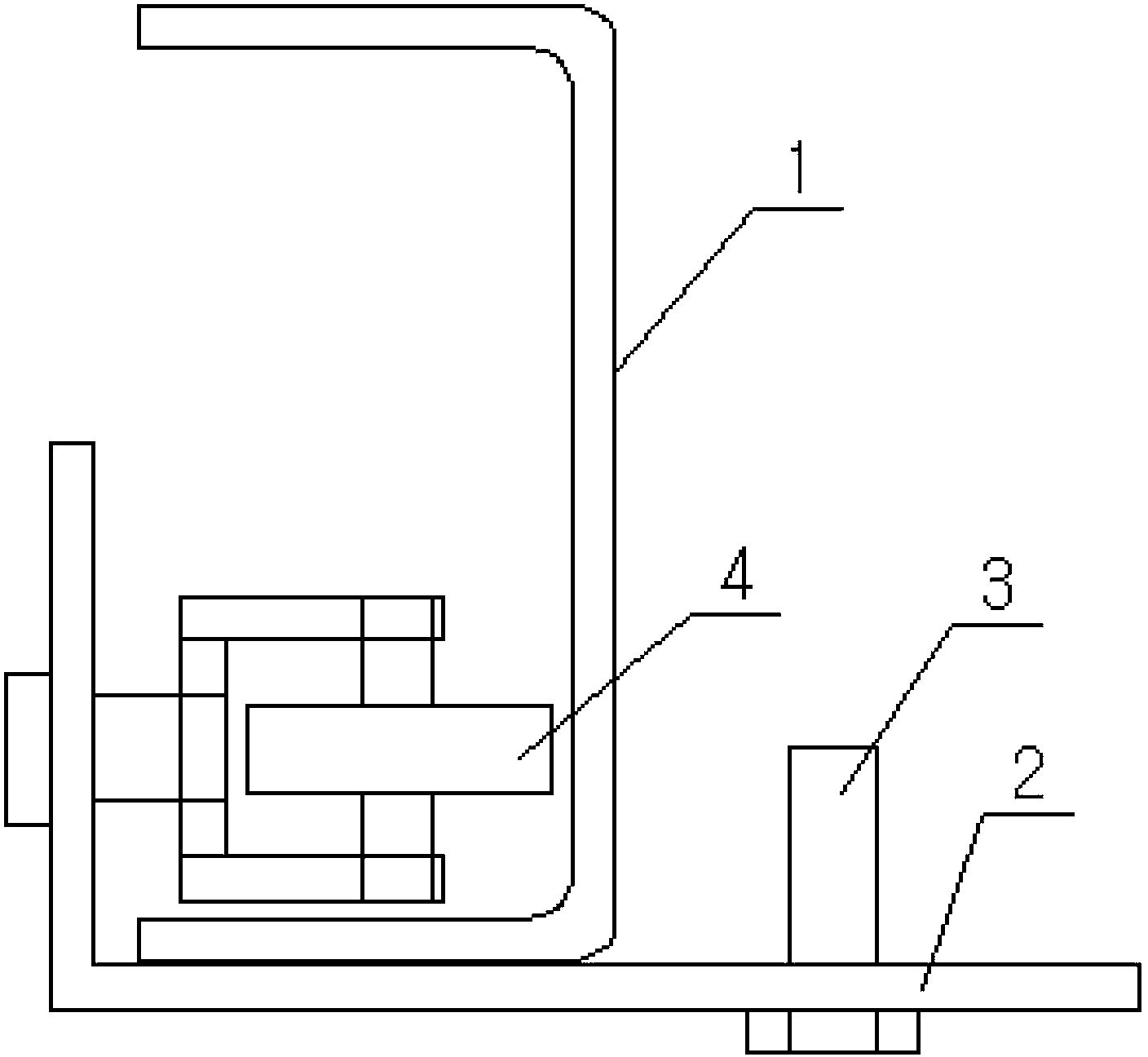
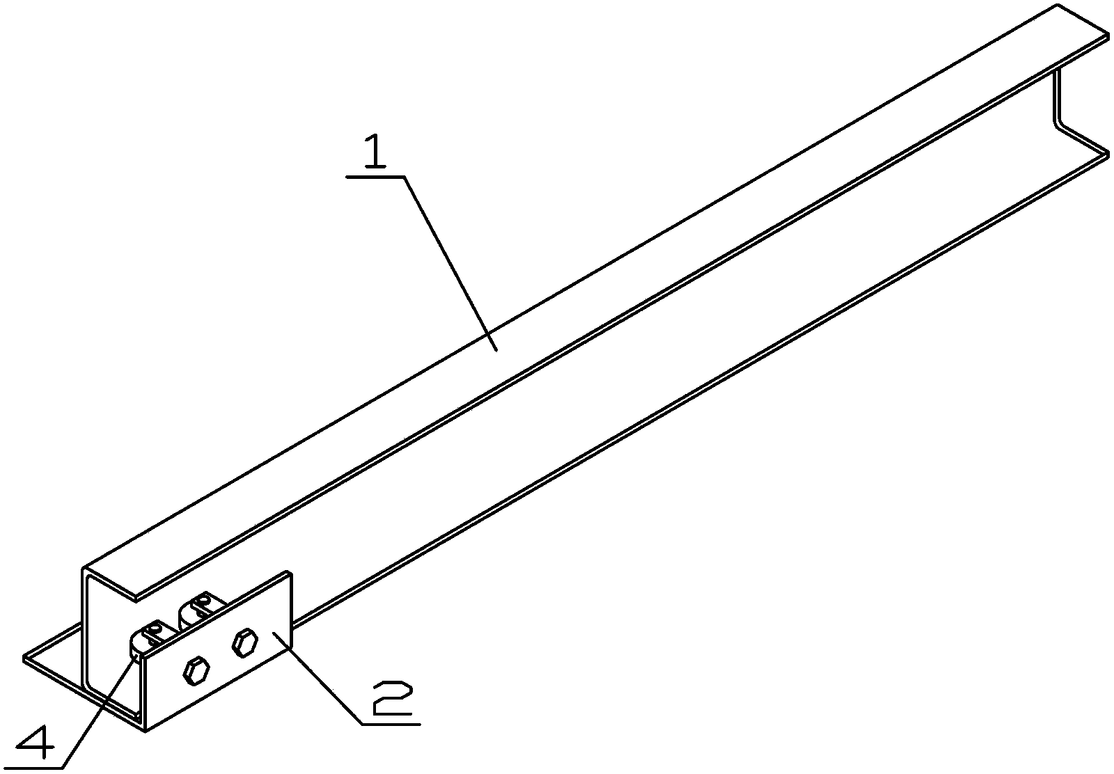
[0022] The present invention as figure 1 with figure 2 As shown, a device used in a method for replacing the wheel set of an overhead crane includes a channel steel guide rail 1 and a slide plate 2, the channel steel guide rail 1 and the slide plate 2 are combined together, the slide plate 2 is an L-shaped plate, and the slide plate 2 A locking bolt 3 is provided on the long board surface of the slide plate 2, and a guide pulley 4 is provided on the short board surface of the slide plate 2, and the slide plate 2 is fixedly connected with the guide pulley 4.

[0023] A method for replacing a wheel set of an overhead crane is completed according to the following steps:

[0024] 1) Use a jack to jack up the car body. After the car body is lifted by 300mm, place the car body support on the inner side close to the wheel set;

[0025] 2) Take back the ja...


PUM


Abstract

The invention relates to a method for replacing a wheel group of a bridge crane. The method comprises the following steps: jacking up a crane body by using a jack and placing a crane body support; returning the crane body to the crane body support; disassembling the wheel group and a connecting screw of a drive wheel; welding a channel steel guide rail on an end beam of the crane; locking a transverse beam and a sliding plate of the wheel group by using a locking bolt and pulling out the wheel group; carrying the wheel group to the ground and entrucking; disassembling a joint and a saddle of the old wheel group and assembling on the new wheel group; and hoisting the wheel group to a walking platform of the crane. Compared with the prior art, the method has the benefits that the characteristics of reasonable structural design and high safety are achieved; the walking wheel group moves along the guide rail through the sliding plate and the guide rail, so the wheel group can move with balance; the operation steps of replacing the wheel group of the bridge crane are simplified; the work intensity and the complex degree are effectively reduced; the production time is saved; the potential safety hazard of the work is eliminated; and personal injury accidents are avoided.

Description

technical field [0001] The invention relates to the mechanical field, in particular to a method and device for replacing a wheel set of an overhead crane. Background technique [0002] The wheel set and balance beam assembly of a large-tonnage bridge crane in a steelmaking plant have a large weight and overall size. Taking a 300t crane as an example, the traveling wheel set weighs about 13t, is 6.3m long, and 1.8m high. When replacing the wheel set, in order to maintain The usual way to balance the wheel set is to hang multiple chain cranes within a small angle range above the wheel set. The operator operates on the side of the wheel set. When the wheel set swings left and right, it will endanger the safety of the workers. The wheel set is under the end beam. When moving in and out, it is easy to dump, and the replacement is technically difficult, heavy workload, and dangerous. The traction and balance of the wheel set is the key to the entire operation process, and it is di...

Claims


Application Information

Patent Timeline
Patent Type & Authority Patents(China)
IPC IPC(8): B66C13/00
Inventor 李新林董维财吴万超胡世雄齐鹏程李芳
Owner ANSHAN IRON & STEEL GROUP CORPORATION
Why Eureka
Try Eureka