Light guiding system, side-inlet type backlight module and liquid crystal display

A light introduction and collection system technology, applied in light guides, instruments, optics, etc., can solve the problems affecting the optical quality of the backlight module, the influence of component functions, and large brightness differences, so as to improve the optical quality, life span, and service life Effect

Inactive Publication Date: 2013-04-17
TCL CHINA STAR OPTOELECTRONICS TECH CO LTD
View PDF5 Cites 7 Cited by
  • Summary
  • Abstract
  • Description
  • Claims
  • Application Information

AI Technical Summary

Problems solved by technology

However, since the light-emitting angle of the light-emitting end 21 of the optical fiber 20 is small (usually less than 60 degrees), the brightness difference between the front of the light-emitting end 21 and the light-emitting end 21 (that is, the left and right sides of the light-emitting end 21) is too large, resulting in bright light. The phenomenon of being dark and clear, when it is serious, the position of each light outlet 21 can be distinguished, which seriously affects the optical quality of the backlight module
In addition, because the ambient light CL contains a certain amount of short-wave light (the wavelength range is about 200nm ~ 400nm), some polymer materials will undergo photochemical reactions under long-term irradiation of short-wave light, and in the backlight module, many components They are all made of polymer materials, so they are very sensitive to short-wave light. If they are irradiated by short-wave light for a long time, the functions of many components will be greatly affected and their lifespan will be reduced.

Method used


Image

  • Light guiding system, side-inlet type backlight module and liquid crystal display
  • Light guiding system, side-inlet type backlight module and liquid crystal display
  • Light guiding system, side-inlet type backlight module and liquid crystal display

Examples


Embodiment 1

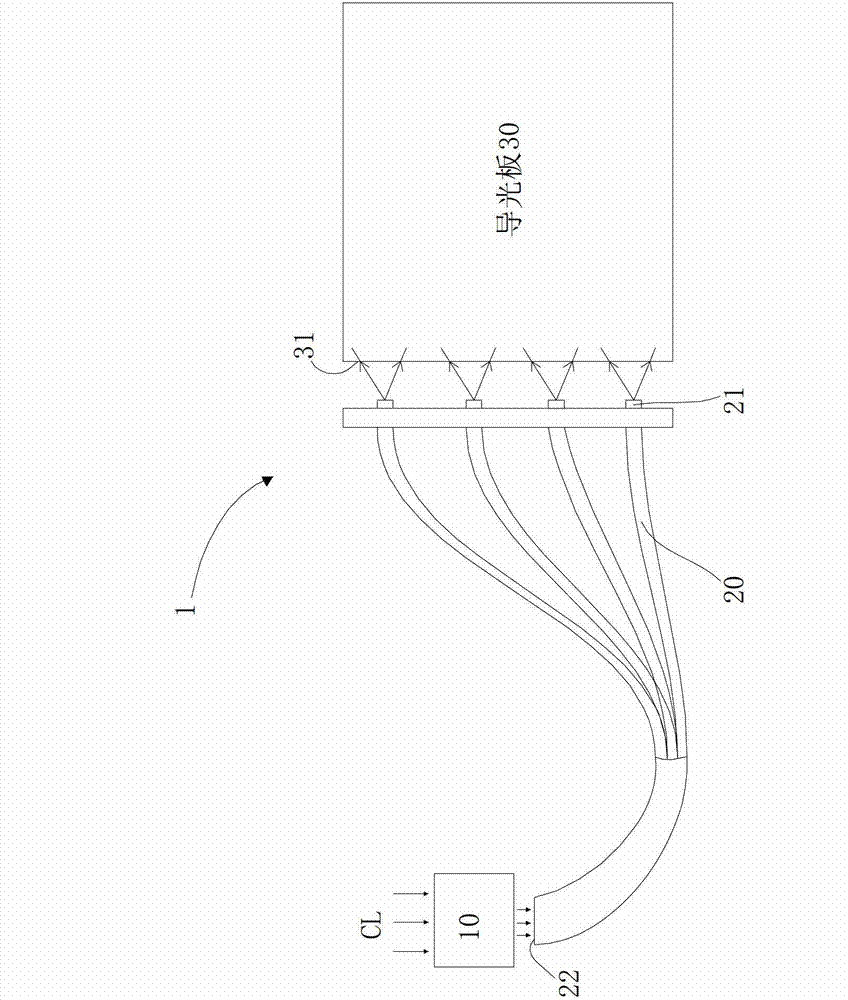
[0024] refer to figure 2 , The light introduction system 1 includes an ambient light collection system 10 , several optical fibers 20 , and a fluorescent film 40 . The ambient light collection system 10 faces and absorbs the ambient light CL. It should be noted that the ambient light CL can be sunlight, light, or light emitted by other luminous objects. Each optical fiber 20 has a light output end 21 and a light input end 22. The light input ends 22 of each optical fiber converge into a bundle and are adjacent to the ambient light collection system 10. The light output ends 21 of each optical fiber are arranged adjacent to the light guide plate 30. The light-incident side 31, it should be noted that the number and arrangement of the light-emitting ends 21 are not the same as figure 2 What is shown in is limited, but the number and arrangement of the light-emitting ends 21 are determined according to the actual situation. The light emitting surface 211 of each light emittin...

Embodiment 2

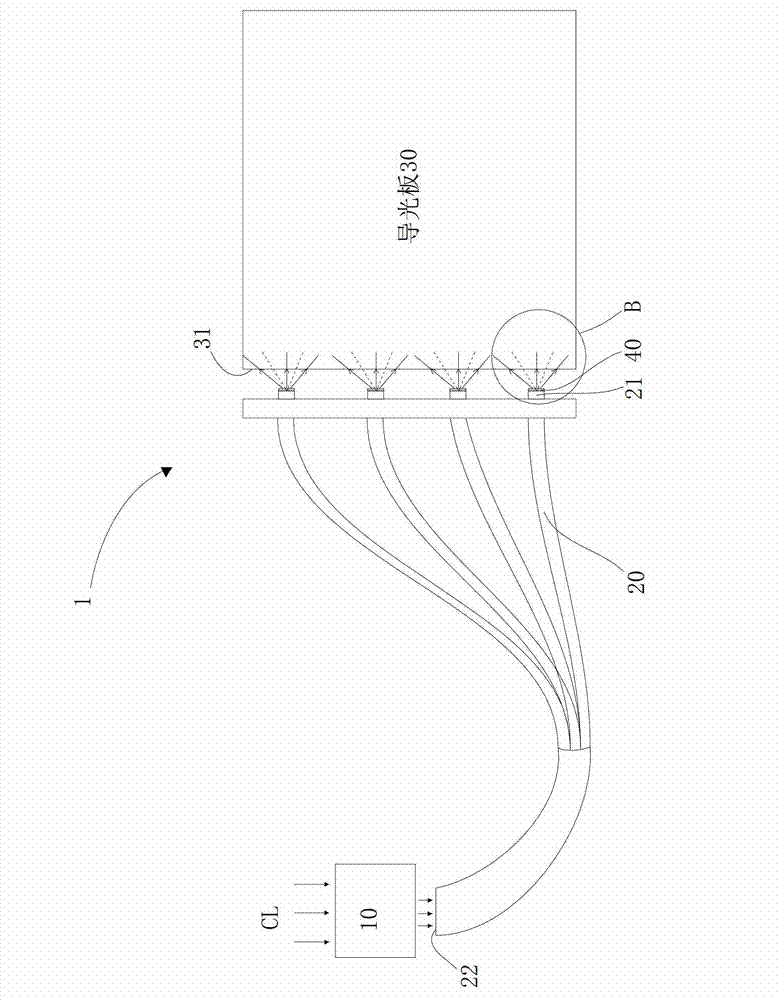
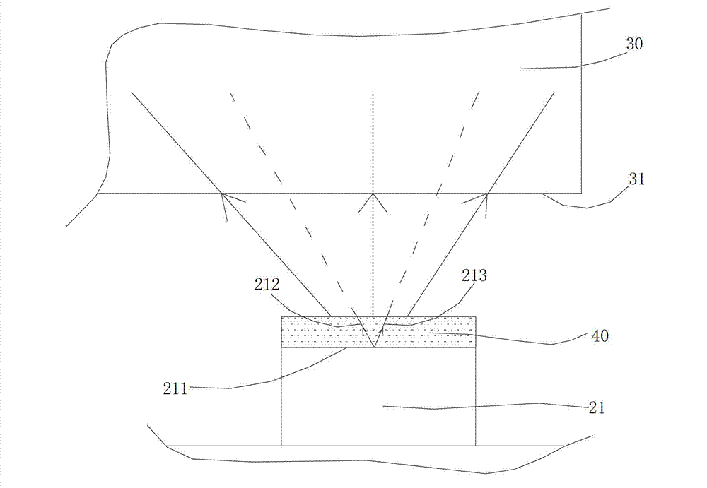
[0029] refer to Figure 4 The difference between Embodiment 2 and Embodiment 1 is that the fluorescent film 40 can also be arranged on the light-incident side 31 of the light guide plate 30, and the scattering particles contained in the fluorescent film 40 will diffuse the light beam passing through the fluorescent film 40, that is, the light 212 , 213 are diffused and spread along the solid line, so that the light beam emitted from the light-emitting surface 211 is diffused.

Embodiment 3

[0031] refer to Figure 5a and Figure 5b , the fluorescent film 40 also has other settings. For example, a cover body 90 can be provided at a position relative to each light-emitting end 21, and the cover body 90 includes an inner wall 91 facing the light-emitting end 21 and an outer surface 92 facing away from the light-emitting end 21, and the fluorescent film 40 can be arranged on the On the inner wall 91 or on the outer surface 92, the scattering particles contained in the fluorescent film 40 diffuse the light beam passing through the fluorescent film 40, that is, the light rays 212, 213 are scattered and diffused and propagate along the solid line, and then the light emitting surface 211 is emitted. beam is diffused. Of course, in this embodiment, the shape of the cover body 90 is not limited to the circle shown in the figure, for example, it can also be oval, square and so on.


PUM

PropertyMeasurementUnit
wavelengthaaaaaaaaaa

Abstract

The invention discloses a light guiding system, a side-inlet type backlight module and a liquid crystal display. The light guiding system comprises an ambient light collection system, a plurality of light guiding devices and a fluorescent film. The ambient light collection system faces ambient light to absorb the ambient light. Every light guiding device is provided with a light inlet end and a light outlet end, the light outlet end is close to a light inlet side of a light guiding plate, the light inlet end is close to the ambient light collection system, and the absorbed ambient light enters into the light inlet end and is transmitted to the light outlet end. The fluorescent film is arranged between the light outlet end and the light inlet side. The fluorescent film enables light beam emitted from the light outlet end to be scattered, so that the phenomenon of uneven brightness of the light beam emitted from the light outlet end on the light inlet side is improved and the optical taste of the side-inlet type backlight module is improved, and moreover, the fluorescent film can convert shortwave light with wavelength of 200nm to 400nm into visible light to prevent parts of the side-inlet type backlight module from being irradiated by the shortwave light, so that the service life of the parts can be prolonged, and the service life of the liquid crystal display can be prolonged.

Description

technical field [0001] The invention relates to the technical field of liquid crystal display, in particular to a light introduction system, a side-entry backlight module and a liquid crystal display. Background technique [0002] Nowadays, most of the backlight modules of LCD (Liquid Crystal Display) use the original light source as the backlight light source. The original light source mentioned here refers to the light source that uses energy such as electricity to make itself illuminate, such as LED. LED has the advantage of high efficiency and energy saving, so it is widely used as a backlight light source in a backlight module. However, as people pay more attention to energy saving and environmental protection, the power consumption of the backlight light source in the current backlight module needs to be further reduced, which requires reducing the number of LEDs used to reduce the power consumption of the backlight light source, or using a new type of energy-saving li...

Claims


Application Information

Patent Timeline
Patent Type & Authority Applications(China)
IPC IPC(8): F21V13/02F21S8/00G02F1/13357F21Y101/02
CPCG02B6/0023G02B6/0028G02B6/0068G02F1/133615G02F1/133614G02F1/133618
Inventor 胡哲彰贺虎
Owner TCL CHINA STAR OPTOELECTRONICS TECH CO LTD
Why Eureka
Try Eureka