
Method for reducing water flow of air conditioning system and dynamic temperature difference flow regulating valve

A flow control valve, control valve technology, applied in heating and ventilation control systems, heating and ventilation safety systems, valve details, etc., can solve problems such as the inability to achieve minimum flow operation

Inactive Publication Date: 2013-04-17
陈建平
View PDF4 Cites 17 Cited by
  • Summary
  • Abstract
  • Description
  • Claims
  • Application Information

AI Technical Summary

Problems solved by technology

[0003] The technical problem to be solved by the present invention is to overcome the problem that in the air-conditioning system where the water flow regulating valve with a constant temperature difference between the inlet and outlet water is installed at the water inlet or outlet pipe of the heat exchange coil, the cooling condition that does not need to consider the dehumidification function is dry work. In order to solve the problem that the minimum flow operation cannot be realized under the heating condition, a method can be provided to realize the minimum flow operation and further reduce the energy consumption of the water pump

Method used


Image

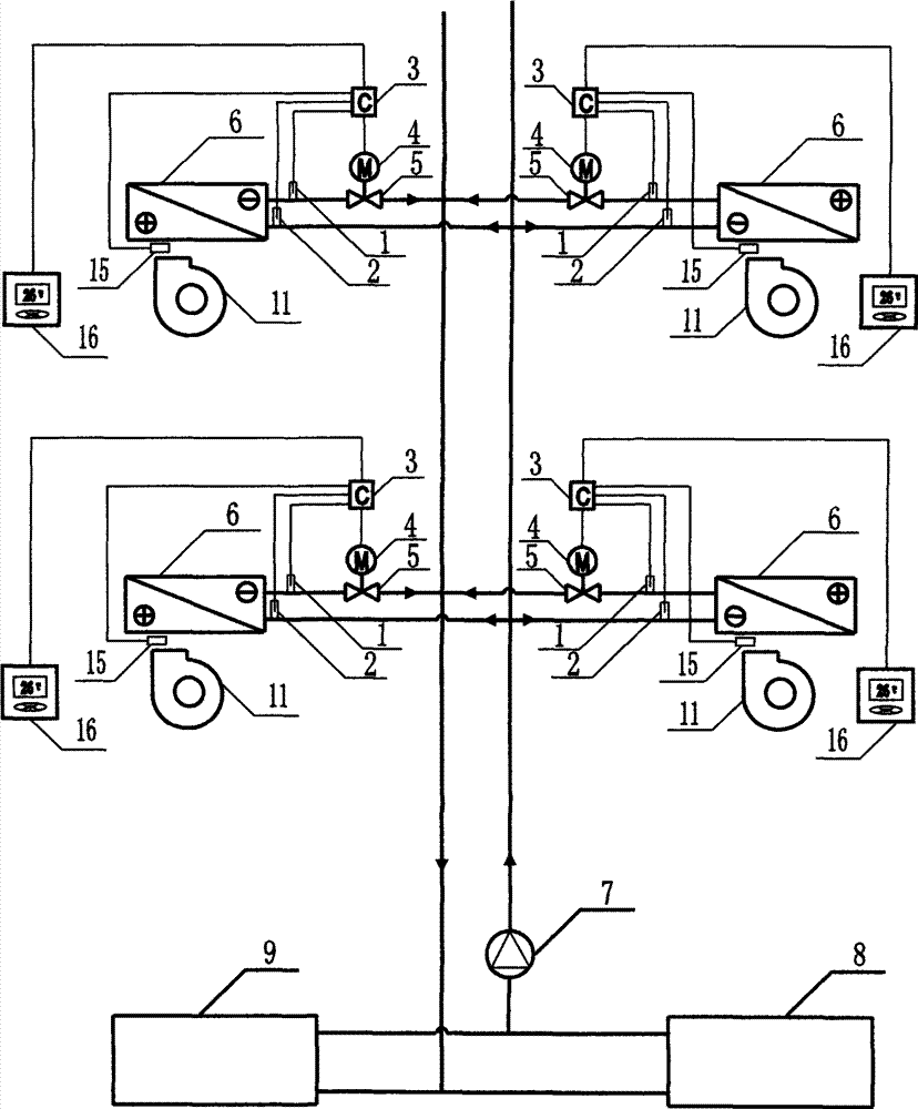
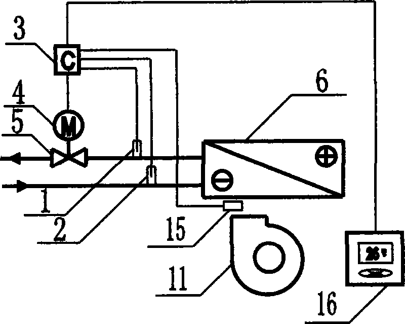
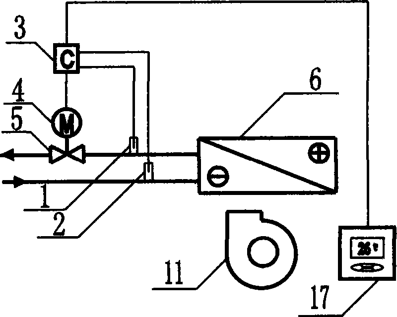
  • Method for reducing water flow of air conditioning system and dynamic temperature difference flow regulating valve
  • Method for reducing water flow of air conditioning system and dynamic temperature difference flow regulating valve
  • Method for reducing water flow of air conditioning system and dynamic temperature difference flow regulating valve

Examples


Embodiment Construction

[0019] The present invention will be described in further detail below in conjunction with the accompanying drawings.

[0020] figure 1 It is a schematic diagram of an air-conditioning system composed of a cooling host 8, a heating host 9, a water pump 7, a fan 11, and a heat exchange coil 6. Through the action of the water pump, water circulates in the system. When it flows through the cooling host 8 Or the water is cooled or heated when heating the host machine 9, and then the water is sent to the heat exchange coil 6 to cool or heat the indoor air, and a dynamic temperature difference flow regulating valve is installed at the water inlet or outlet pipe of the heat exchange coil 6 to Realization: In the cooling condition, the temperature difference between the inlet and outlet water is always maintained at the optimal value, which can not only ensure the cooling and dehumidification effect of the heat exchange coil, but also avoid the phenomenon of large flow and small tempe...


PUM


Abstract

The invention discloses a method for reducing a water flow of an air conditioning system and a dynamic temperature difference flow regulating valve. The air conditioning system is composed of devices of a cooling main machine, a heating main machine, a water pump, a fan, a heat exchanging coil pipe and the like. The dynamic temperature difference flow regulating valve comprises a water flow regulating valve, a driver, heat exchanging coil pipe water inlet and outlet temperature sensors, a controller, an indoor air temperature sensor, an indoor air temperature setting device or an indoor cooling and heating load calculator. In the cooling work condition, the controller independently runs after the temperature sensors detect water temperatures and always keeps temperature difference of inlet and outlet water to be at the optimum value so that cooling and dehumidification effects can be guaranteed, and the phenomenon that large flow and small temperature difference occur to a water system is avoided; in the dry cooling work condition or the heating work condition, the controller always keeps the temperature difference of the inlet and outlet water to be at the maximum value according to the indoor air temperature sensor and the indoor air temperature setting device or the indoor cooling and heating load calculator, namely, the dynamic temperature difference flow regulating valve can achieve minimum flow operation in multiple work conditions, and energy consumption of the water pump is further reduced.

Description

technical field [0001] The invention relates to a method for reducing water flow in an air-conditioning system composed of a cooling main engine, a heating main engine, a water pump, a fan, a heat exchange coil, and a dynamic temperature difference flow regulating valve for realizing the method. Background technique [0002] On April 29, 2009, I applied for the Chinese invention patent "A Method and Device for Energy Saving of Air-Conditioning System", application number: CN200910131032.4. Install a water flow regulating valve with a constant temperature difference between the inlet and outlet water to realize the automatic adjustment of the water volume when the air flow and air temperature on the air side of the heat exchange coil change, so as to keep the temperature difference between the inlet and outlet water constant, which is required by the design of the air conditioning system The optimal temperature difference value can reduce the water flow of the system and incr...

Claims


Application Information

Patent Timeline
IPC IPC(8): F24F11/02F16K31/64
Inventor 陈建平
Owner 陈建平
Learn More