
Method for changing number of tube passes of tube type heat exchanger

A tube-and-tube heat exchanger and heat exchanger technology, which is applied to the types of heat exchangers, heat exchanger shells, indirect heat exchangers, etc., can solve the problems of heavy workload and large investment in transformation, and achieve simple transformation methods , good effect

Active Publication Date: 2013-04-17
SHANGHAI HUIDE ENERGY INTEGRATION TECH
View PDF4 Cites 8 Cited by
  • Summary
  • Abstract
  • Description
  • Claims
  • Application Information

AI Technical Summary

Problems solved by technology

After the heat exchanger is put into use, because the flow rate, type or nature of the material is inconsistent with the original design working conditions, it is necessary to change the number of tube passes of the existing heat exchanger to meet the new requirements. The general method is to replace the entire unit The heat exchanger or the tube bundle and the tube box are replaced at the same time. This method requires a lot of work and a large investment

Method used


Image

  • Method for changing number of tube passes of tube type heat exchanger
  • Method for changing number of tube passes of tube type heat exchanger
  • Method for changing number of tube passes of tube type heat exchanger

Examples


Embodiment 1

[0024] Embodiment 1: A modification method for the number of tube passes of a two-tube shell-and-tube heat exchanger.

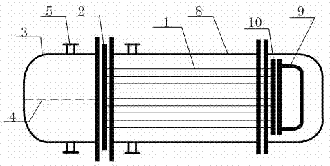
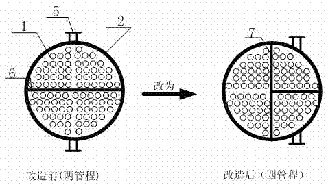
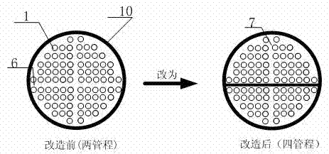
[0025] Such as figure 1 As shown, the existing tube-and-tube heat exchanger consists of a tube bundle 1, a first tube plate 2, a tube box with a nozzle side with a nozzle side 3, a nozzle 5, a groove or rib 6, and a side without a nozzle without a tube The nozzle side pipe box 9 and the second tube plate 10 are composed, wherein: the pipe nozzle 5 is welded on the outside of the nozzle side pipe box 3, and the inside of the two nozzle side pipe boxes 3 and 9 are welded with partitions 4. There are generally 2-4 nozzles 5, the tube bundle 1 is located in the shell 8, and the two ends of the tube bundle 1 are respectively connected to the first tube sheet 2 and the second tube sheet 10, and the first tube sheet 2 and the second tube sheet 10 Grooves or ribs 6 are provided on the top.

[0026] Such as figure 2 , 3 , 4 and 5, the transformation method is fir...

Embodiment 2

[0030] Embodiment 2: A modification method for the number of tube passes of a four-tube shell-and-tube heat exchanger.

[0031] Such as figure 1As shown, the existing tube-and-tube heat exchanger consists of a tube bundle 1, a first tube plate 2, a tube box with a nozzle side with a nozzle side 3, a nozzle 5, a groove or rib 6, and a side without a nozzle without a tube The nozzle side pipe box 9 and the second tube plate 10 are composed, wherein: the pipe nozzle 5 is welded on the outside of the nozzle side pipe box 3, and the inside of the two nozzle side pipe boxes 3 and 9 are welded with partitions 4. There are generally 2-4 nozzles 5, the tube bundle 1 is located in the shell 8, and the two ends of the tube bundle 1 are respectively connected to the first tube sheet 2 and the second tube sheet 10, and the first tube sheet 2 and the second tube sheet 10 Grooves or ribs 6 are provided on the top.

[0032] Such as Image 6 , 7 , 8 and 9, the transformation method is firs...


PUM


Abstract

The invention relates to a method for changing number of tube passes of a tube type heat exchanger. As for traditional methods, an entire heat exchanger or a tube bundle and a tube box is / are replaced, the changing workload is high, and the costs are high. The method includes changing a tube plate and the tube box, the changing workload is low, and the costs are low. A groove or a protruded rib is arranged on the tube plate of the tube bundle of the heat exchanger, the groove or the protruded rib is required to be partially or totally filled, and a novel groove or a novel protruded rib is added. The structure of the tube box is required to be changed in two aspects that a partition board on the inner side is changed, existing partition boards are required to be partially or totally removed, and novel partition boards can be added according to requirements as well; and a position of a tube nozzle on the outer side is changed. By means of the method for changing the heat exchanger, the number of tube passes of the heat exchanger can be changed, the tube bundle of the heat exchanger or the entire heat exchanger is not required to be replaced, and changing costs and construction workload can be substantially reduced.

Description

technical field [0001] The invention relates to a method for transforming the number of tube passes of a tube-and-tube heat exchanger. Background technique [0002] The shell and tube heat exchanger is a kind of equipment commonly used in the industry for the heat exchange of two fluids. It is mainly composed of three parts: the shell, the tube bundle and the tube box. The tube bundle and the tube box form the space for the material flow in the tube side. According to the needs of fluid heat transfer and flow rate, the space for material flow in the tube side is divided into 1-8 flow spaces with basically equal flow areas by the tube sheet in the tube box. Each flow space is connected in series from end to end and connected to the inlet and outlet. After the heat exchanger is put into use, because the flow rate, type or nature of the material is inconsistent with the original design working conditions, it is necessary to change the number of tube passes of the existing heat...

Claims


Application Information

Patent Timeline
IPC IPC(8): F28D7/16F28F9/02
Inventor 张高博常刚
Owner SHANGHAI HUIDE ENERGY INTEGRATION TECH
Learn More