
OBS (optical back scattering) working state detector

A working state and detector technology, which is applied in the direction of measuring devices, scientific instruments, suspension and porous material analysis, etc., can solve the problems of data interruption, the inability of operators to know the working state, and the impact on the quality of results, etc., and achieve strong anti-interference ability Effect

Active Publication Date: 2014-09-10
BUREAU OF HYDROLOGY CHANGJIANG WATER RESOURCES COMMISSION
View PDF4 Cites 0 Cited by
  • Summary
  • Abstract
  • Description
  • Claims
  • Application Information

AI Technical Summary

Problems solved by technology

[0005] In view of the above problems, the object of the present invention is to provide an OBS working state detector, which aims to solve the technical problem that the operator cannot know the working state of the existing OBS when it is working, which may cause data interruption and affect the quality of the results.

Method used


Image

  • OBS (optical back scattering) working state detector
  • OBS (optical back scattering) working state detector
  • OBS (optical back scattering) working state detector

Examples


Embodiment 1

[0026] figure 1 The structure of the OBS working state detector provided by the first embodiment of the present invention is shown. For ease of description, only the parts related to the embodiment of the present invention are shown.

[0027] The OBS working status detector provided in this embodiment includes:

[0028] The photosensitive receiving component 1 is used to sense the infrared modulation signal sent by the OBS and generate an induced current;

[0029] The preamplifier 2 is used to amplify the induced current generated by the photosensitive receiving component 1;

[0030] Automatic gain controller 3, used to stabilize the amplification factor of the induced current;

[0031] Band pass filter 4 is used to filter out interference signals in the amplified induced current;

[0032] The demodulator 5 is used to demodulate a weak AC signal from the filtered induced current;

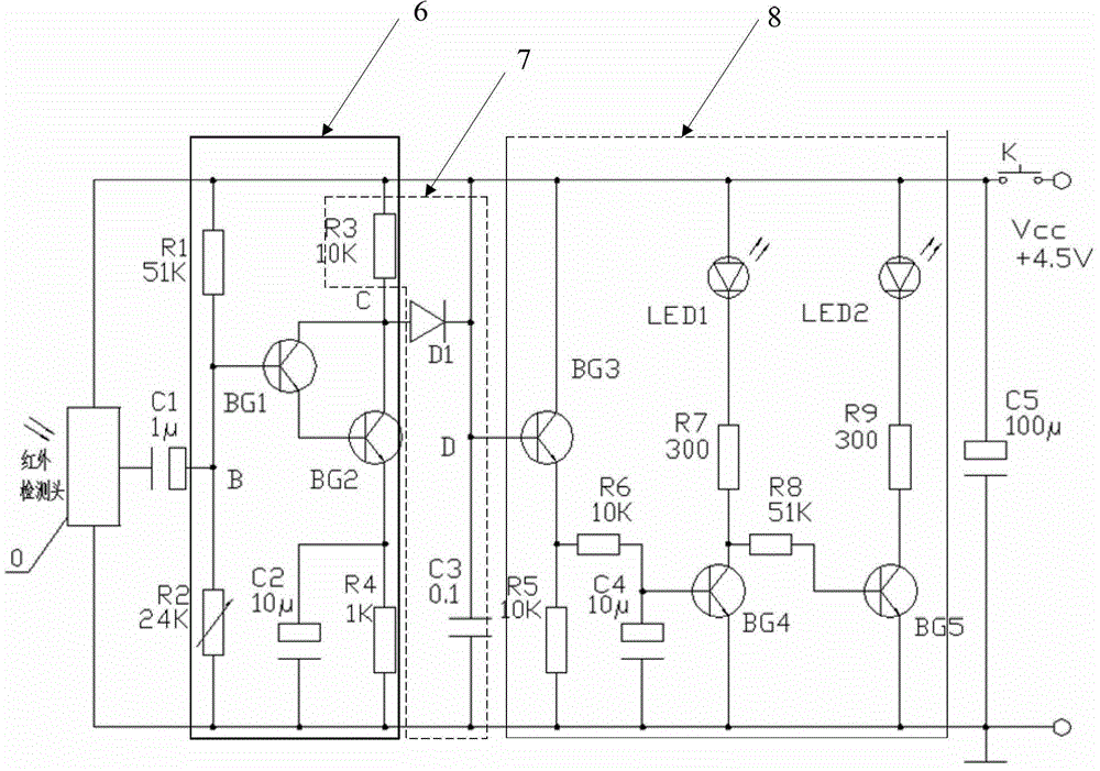
[0033] AC amplifier circuit 6 for amplifying the demodulated AC signal;

[0034] The detection integration ci...

Embodiment 2

[0039] figure 2 The structure of the OBS working state detector provided by the second embodiment of the present invention is shown. For ease of description, only the parts related to the embodiment of the present invention are shown.

[0040] The OBS working state detector provided in this embodiment includes the photosensitive receiving component 1, the preamplifier 2, the automatic gain controller 3, the band pass filter 4, the demodulator 5, and the AC amplifier circuit 6, as described in the first embodiment. The detection integration circuit 7 and the driving display circuit 8 can be integrated into the photosensitive receiving part 1, the preamplifier 2, the automatic gain controller 3, the band pass filter 4, and the demodulator 5. In infrared detection head 0, when OBS is working, a series of infrared modulation signals are periodically sent out. Its infrared wavelength is 875nm and modulation frequency is 500Hz. After infrared detection head 0 detects this signal, its o...


PUM


Abstract

The invention is applicable in the field of suspended sediment concentration detection, and provides an OBS (optical back scattering) working state detector. The OBS working state detector comprises a light-sensitive receiving component, a preamplifier, an automatic gain controller, a band-pass filter, a demodulator, an AC amplifying circuit, a rectifying integrating circuit and a drive display circuit, which are connected in sequence. According to the technical scheme, a series of infrared modulation signals are emitted during OBS operation, the light-sensitive receiving component receives the signals and then generates induced currents, the induced currents go through the preamplifier, the automatic gain controller, the band-pass filter and the demodulator, resulting in weak AC signals, the weak AC signals are further subjected to AC amplification and processed by the rectifying integrating circuit to produce drive currents, and the drive currents drive the drive display circuit; and an operator can determine the OBS working state according to the state of the drive display circuit. Accordingly, the nondestructive detection of infrared signals of OBS is completed.

Description

Technical field [0001] The invention belongs to the field of suspended sand concentration detection, and in particular relates to an OBS working state detector. Background technique [0002] The traditional observation of suspended sediment concentration is mainly to collect water samples on site for indoor analysis. This method has the advantage of directly obtaining the suspended sediment concentration, but the sampling is labor-intensive, the analysis time is long, and due to the large time and space interval, it is easy to miss The peak value of the suspended sediment concentration during the amplitude change. Therefore, OBS (Optical Back Scattering), which monitors suspended matter through the scattering of infrared radiation, and then measures water turbidity and sediment concentration, has become an important means of international suspended sediment observation. [0003] The core of OBS is an infrared optical sensor, which mainly measures the concentration of suspended mat...

Claims


Application Information

Patent Timeline
Patent Type & Authority Patents(China)
IPC IPC(8): G01N15/06
Inventor 万正松田淳许宝华周年华沙剑徐海东赵辉杜国元叶建伟
Owner BUREAU OF HYDROLOGY CHANGJIANG WATER RESOURCES COMMISSION
Learn More