
Zoom optical system

A technology of optical system and electronic monitoring system, which is applied in optics, optical components, instruments, etc., can solve the problem of not optimizing the focal length and resolution of the macro, unable to meet the high demand of the zoom lens, and not optimizing the zoom ratio of the macro and emphasis, to achieve the effect of saving the number of lens barrels, simplifying the structure, and improving optical performance

Active Publication Date: 2013-04-17
JIANGXI PHENIX OPTICS TECH CO LTD
View PDF5 Cites 11 Cited by
  • Summary
  • Abstract
  • Description
  • Claims
  • Application Information

AI Technical Summary

Problems solved by technology

[0003] Usually, the small zoom optical system only emphasizes its focal length and resolution when the object distance is infinite, and does not specifically optimize the focal length and resolution when the macro is used, so it can only ensure that the object distance is infinite. Zoom ratio and resolution;
[0004] While the large zoom optical system is designed to focus on optimizing the resolution at infinity object distance and macro distance at the same time, it does not make special requirements on the focal length of macro distance, so it can only guarantee the optical system at different object distances. Resolving Power and Zoom Ratio of the Lens at Infinity Object Distance
[0005] The above two types of zoom optical systems only realize the zoom ratio characteristics of the optical system when the object distance is infinite, without optimizing and emphasizing the macro zoom ratio, which cannot meet the market's higher demand for zoom lenses

Method used


Image

  • Zoom optical system
  • Zoom optical system
  • Zoom optical system

Examples


Embodiment Construction

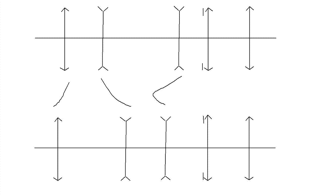
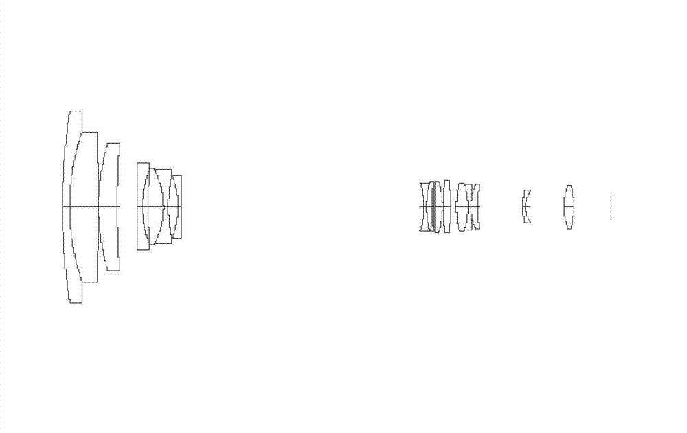
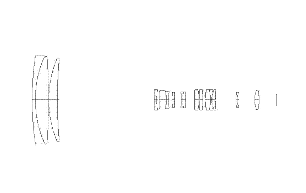
[0041] figure 1 Shown is a zoom schematic diagram of the present invention, a zoom optical system, an electric zoom lens for an electronic monitoring system, suitable for two photosensitive devices of a CMOS photosensitive sheet or a CCD chip, including:

[0042] The first lens group G1 with refractive power, the second lens group G2 with negative refractive power, the third lens group G3 with negative refractive power arranged in order from the object side to the image side, fixed on the fourth lens group G4 close to G3 The side stop ST, the fourth lens group G4 with positive refractive power, the fifth lens group G5 with positive refractive power;

[0043] Among them, the positions of the first lens group G1, the second lens group G2 and the third lens group G3 relative to the photosensitive device are changed during the zooming process, and the positions of the fourth lens group G4 and the fifth lens group G5 are relative to each other during the zooming process. The posit...


PUM


Abstract

The invention discloses an electric zoom lens for electronic monitoring systems. The electric zoom lens is suitable for sensitization devices, such as a CMOS (Complementary Metal-Oxide-Semiconductor) photographic plate or a CCD (Charge Coupled Device) chip. The electric zoom lens is provided with a first lens group with refraction, a second lens group with negative refraction, a third lens group with negative refraction, a fourth lens group with positive refraction and a fifth lens group with positive refraction, which are orderly arranged from an object space to an image space, wherein the positions of the first lens group, the second lens group and the third lens group are variable relative to the sensitization device during a zooming process, and the positions of the fourth lens group and the fifth lens group are fixed relative to the sensitization device during the zoom process. The zoom optical system provided by the invention realizes different zoom ratios under different object distances, and can realize 20x zoom in an infinity object distance and 20x zoom in a 3m object distance; and meanwhile, the optical system further has the characteristics of high resolution, low cost and long back focal length, and the like.

Description

technical field [0001] The invention relates to a zoom optical system, in particular to a zoom optical system capable of realizing different zoom ratios at infinity object distance and macro distance. Background technique [0002] At present, medium and large electric zoom lenses for security monitoring generally have disadvantages such as small magnification, low pixels, and high price. With the application and popularization of high-definition video surveillance systems, the limitations of these low-pixel and small-magnification electric zoom lenses popular in the market are becoming more and more obvious. Therefore, new electric zoom lenses with high magnification, high pixels and low cost will become a new trend in the market. [0003] Usually, the small zoom optical system only emphasizes its focal length and resolution when the object distance is infinite, and does not specifically optimize the focal length and resolution when the macro is used, so it can only ensure ...

Claims


Application Information

Patent Timeline
IPC IPC(8): G02B15/17G02B15/14
Inventor 胡长涛粱宏皓郑德裕刘洪海王瑶
Owner JIANGXI PHENIX OPTICS TECH CO LTD
Learn More