
Reactor and method of manufacturing the same

A reactor, constructed technology, applied in inductor/transformer/magnet manufacturing, inductors, fixed inductors, etc., can solve the problems of increased manufacturing facility cost and space requirements, and achieve the effect of low cost

Inactive Publication Date: 2013-04-17
SUMITOMO WIRING SYST LTD
View PDF8 Cites 14 Cited by
  • Summary
  • Abstract
  • Description
  • Claims
  • Application Information

AI Technical Summary

Problems solved by technology

Therefore, multiple adhesive fixing jigs and heat hardening baths must be prepared for mass production, with a corresponding increase in cost and space requirements in the manufacturing facility

Method used


Image

  • Reactor and method of manufacturing the same
  • Reactor and method of manufacturing the same
  • Reactor and method of manufacturing the same

Examples


Embodiment Construction

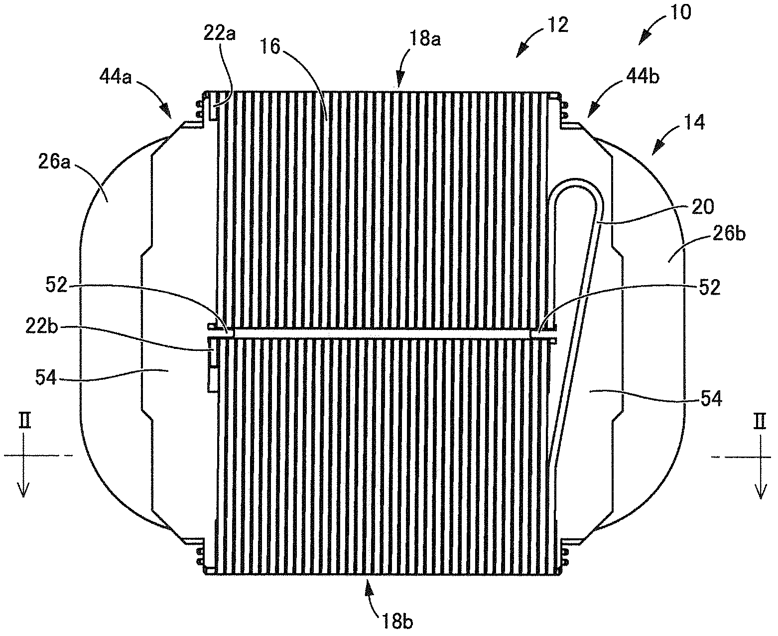
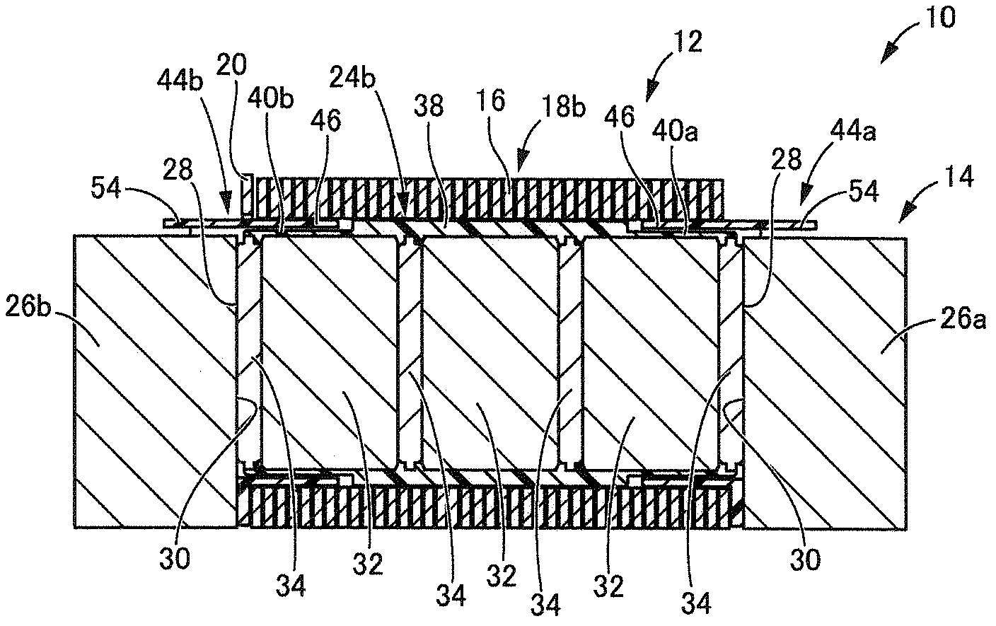
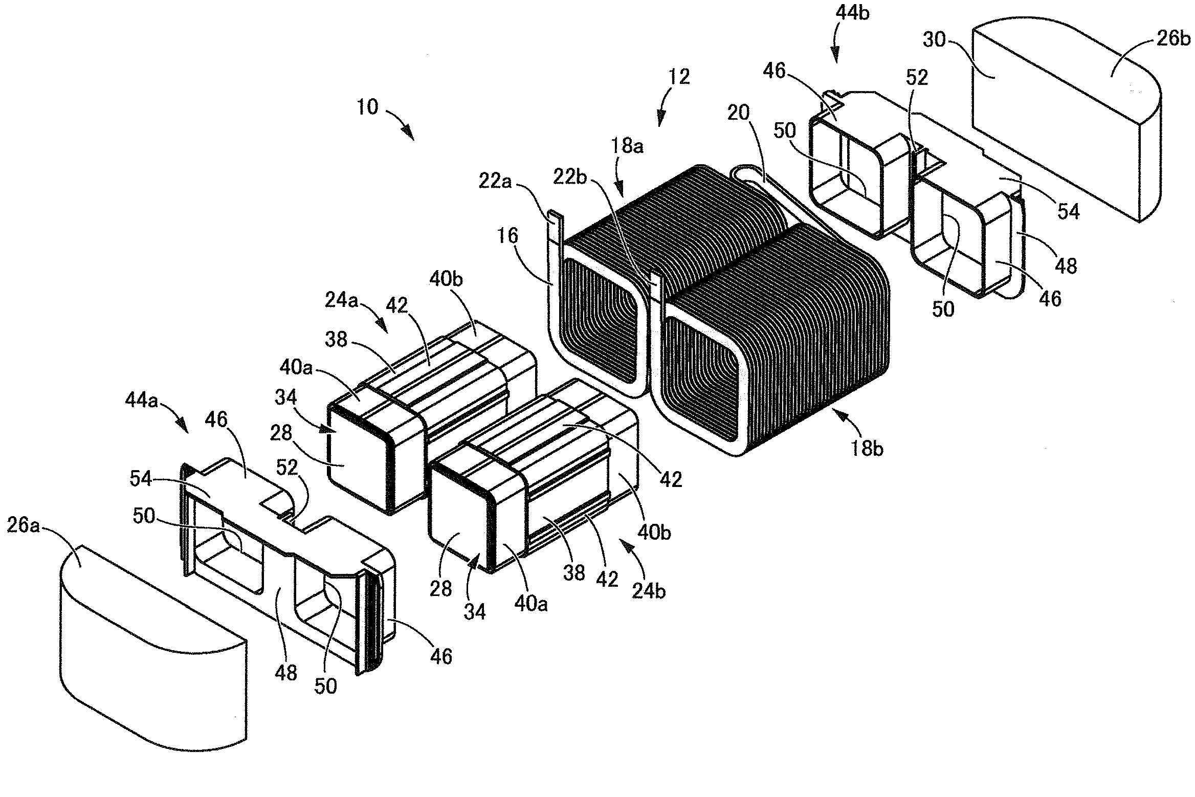
[0035] Figures 1 to 3 A reactor 10 of a first embodiment of the present invention is shown. The reactor 10 includes a coil 12 and an annular core 14 on which the coil 12 is wound. In the following description, the installation side ( figure 2 The lower side in ) is defined as the bottom, and its opposite side is defined as the top.

[0036]The coil 12 includes: a pair of coil elements 18a, 18b formed by winding a continuous winding wire 16 without any joining portion in a spiral shape; and a coil coupling portion 20, The coil coupling part 20 couples the coil elements 18a, 18b. The coil elements 18a, 18b have the same number of turns, and they have a substantially rectangular shape when viewed in the axial direction. The coil elements 18 a , 18 b are arranged side by side so that their axes are parallel to each other, and a portion of the winding wire 16 on one end of the coil 12 is bent into a U shape to form the coil coupling portion 20 . In this configuration, the wi...


PUM

PropertyMeasurementUnit
thicknessaaaaaaaaaa

Abstract

An annular core (14) of a reactor (10) has two core mold members (24a, 24b) integrated by bonding core segments (32) and gap plates (34) with a cyanoacrylate-based adhesive agent (36) to each other and insert-molding the bonded core segments (32) and gap plates (34) with a thermoplastic resin (38).

Description

technical field [0001] The present invention relates to a reactor used as a component of a power converter such as a DC-DC converter mounted on a hybrid vehicle. Background technique [0002] In recent years, due to increased awareness of environmental issues, hybrid or electric vehicles employing an electric motor as a power source in addition to or instead of an engine have become increasingly common. These vehicles include a reactor for stepping up the voltage from a DC power source to a driving voltage for the electric motor. [0003] For example, as described in JP-A-2008-263062 or JP-A-2010-245457, a reactor has a coil wound around an annular core. The reactor includes a switching circuit that takes out a high voltage using counter electromotive force by repeatedly turning on-off the power supply to the coil. [0004] The annular core has a plurality of core segments formed of a magnetic material, and a non-magnetic gap plate is interposed between the core segments t...

Claims


Application Information

Patent Timeline
Patent Type & Authority Applications(China)
IPC IPC(8): H01F17/06H01F27/24H01F41/02H01F27/30H01F41/00
CPCH01F17/06H01F27/263H01F27/306H01F27/325H01F2017/048Y10T29/4902
Inventor 俵秀男薮谷博美鬼塚孝浩大石明典
Owner SUMITOMO WIRING SYST LTD
Learn More