High-frequency high-voltage transformer structure

A high-frequency, high-voltage, transformer technology, applied in the direction of fixed transformer or mutual inductance, transformer/inductor core, transformer/inductor coil/winding/connection, etc. Distributed capacitance, the effect of reducing the voltage between slots

Inactive Publication Date: 2013-04-17
INST OF ELECTRICAL ENG CHINESE ACAD OF SCI
View PDF7 Cites 15 Cited by
  • Summary
  • Abstract
  • Description
  • Claims
  • Application Information

AI Technical Summary

Problems solved by technology

[0004] The purpose of the present invention is to reduce the leakage inductance and distributed capacitance of existing high-frequency high-voltage transformers, realize the miniaturization of transformers, solve the problem of inconvenient maintenance, and propose a structure of high-frequency high-voltage transformers

Method used


Image

  • High-frequency high-voltage transformer structure
  • High-frequency high-voltage transformer structure
  • High-frequency high-voltage transformer structure

Examples


Embodiment Construction

[0014] The present invention will be described in detail below in conjunction with the accompanying drawings and specific embodiments.

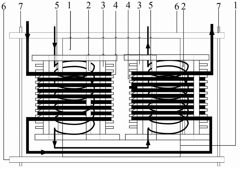
[0015] like figure 1 As shown, the present invention includes two transformer U-shaped magnetic cores 1, two transformer secondary winding bobbins 2, two transformer primary winding bobbins 3, two transformer secondary windings 4, two transformer primary windings 5, and A set of transformer fastening fixtures consists of six components. The transformer core adopts two U-shaped cores that can be connected. The material of the U-shaped core depends on the operating frequency of the designed transformer. Usually, high-frequency transformers can choose ferrite cores, amorphous cores or nanocrystalline cores. Class magnetic core. The purpose of using two U-shaped magnetic cores that can be connected is to easily remove and replace the primary and secondary windings; the primary and secondary winding frames of the transformer are made of insulati...


PUM


Abstract

Disclosed is a high-frequency high-voltage transformer structure. A magnetic core of a transformer comprises two U-shaped magnetic cores (1) in butt joint, primary windings (5) and secondary windings (4) are respectively provided with a two-section structure and are wound on two primary winding frameworks (3) and two secondary winding frameworks (2) respectively, and the secondary winding frameworks (2) are sleeved outside the primary winding frameworks (3) to form a coaxial structure. The two primary winding frameworks and the two secondary winding frameworks are sleeved on magnetic arms in the height direction of the U-shaped magnetic cores (1), the primary windings are connected in series, the secondary windings are connected in series, and magnetic force lines generated by the windings are in the same direction in the magnetic cores by a series connection direction. The primary windings and the magnetic cores (1) of the transformer are insulated by the primary winding frameworks (3), and the secondary windings and the primary windings are insulated by the wall thicknesses of the secondary winding frameworks (2) and gaps among the primary windings (5) and the inner walls of the secondary winding frameworks. By the aid of a set of fixtures (6 and 7), the two magnetic cores in butt joint are clamped, and the transformer is fixed.

Description

technical field [0001] The invention relates to a high-frequency high-voltage transformer. Background technique [0002] With the development of power conversion technology, the power density and output voltage of high-frequency high-voltage power supplies are getting higher and higher, and the operating frequency of power supplies is also increasing. As an important part of the high-frequency high-voltage power supply, the high-frequency high-voltage transformer is a key link that affects the voltage output and power density of the power supply. At the same time, at a high operating frequency, the existence of parasitic or distributed parameters of the high-voltage transformer will directly affect the power inverter. Switching process or system design parameters of the transformer, if the parasitic and distributed parameters of the high-frequency high-voltage transformer cannot be used in the power parameter design, the parasitic and distributed parameters should be minimiz...

Claims


Application Information

Patent Timeline
Patent Type & Authority Applications(China)
IPC IPC(8): H01F19/04H01F27/30H01F27/28H01F27/26
Inventor 高迎慧严萍
Owner INST OF ELECTRICAL ENG CHINESE ACAD OF SCI
Why Eureka
Try Eureka