Transformer for heating high-voltage high-current lamp filaments

A transformer, high current technology, applied in the field of transformers, can solve the problems of increasing the distance between the secondary winding and the magnetic core, increasing the leakage inductance, reducing the efficiency of the transformer, etc. compressive effect

Active Publication Date: 2016-03-23
AVIC BEIJING AERONAUTICAL MFG TECH RES INST
View PDF9 Cites 5 Cited by
  • Summary
  • Abstract
  • Description
  • Claims
  • Application Information

AI Technical Summary

Problems solved by technology

[0004] The disadvantages of this traditional transformer for filament heating are as follows: 1. When the "U" or "C" magnetic core is used for butt jointing, the magnetic core is difficult to achieve the ideal contact state, and there is still gas on the magnetic circuit of the magnetic core. The existence of the air gap, on the one hand, increases the reluctance of the magnetic core, resulting in increased magnetic loss and reduced transformer efficiency; on the other hand, the magnetic field lines generated by the coil are scattered in the air, and the leakage inductance of the transformer increases
2. The outer sleeve-type insulating skeleton is often made of insulating materials such as polytetrafluoroethylene, which is a hollow columnar body with multiple annular grooves. In order to effectively improve the withstand voltage level, the thickness of the insulating sleeve is generally large, resulting in side effects. As the distance between the side winding and the magnetic core increases, the leakage inductance of the transformer increases accordingly
3. Conventional wires are used as the secondary winding. Considering that the output current is increased by increasing the diameter of the winding, there are disadvantages such as winding difficulties and the corresponding increase in the distance between the secondary winding and the magnetic core, which leads to increased leakage inductance. Therefore, in order to effectively increase the upper limit of the output current of the transformer, it is necessary to reasonably improve the form of the secondary winding

Method used


Image

  • Transformer for heating high-voltage high-current lamp filaments
  • Transformer for heating high-voltage high-current lamp filaments
  • Transformer for heating high-voltage high-current lamp filaments

Examples


Embodiment Construction

[0032] In order to have a clearer understanding of the technical features, purposes and effects of the present invention, the specific implementation manners of the present invention will now be described with reference to the accompanying drawings.

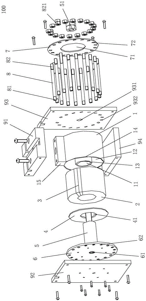
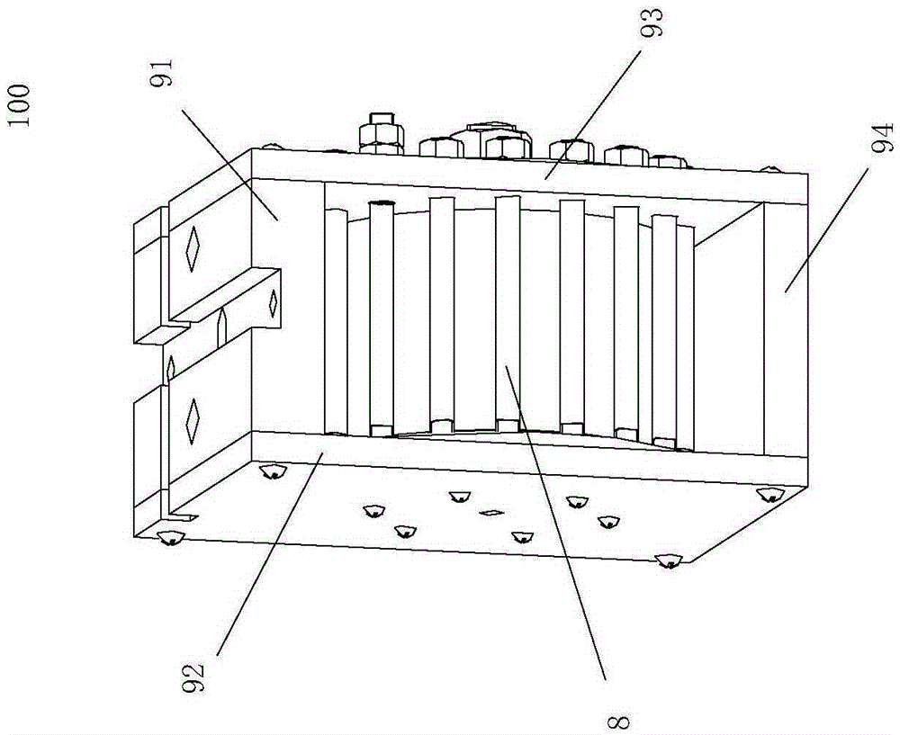
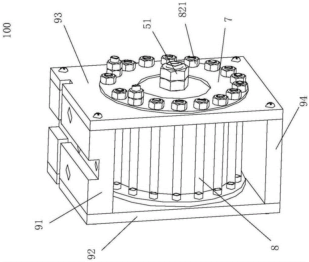
[0033] Such as figure 1 , figure 2 , image 3 with Figure 4 As shown, the present invention proposes a transformer 100 for heating high-voltage and high-current filaments. The transformer 100 includes:

[0034] An insulating housing 1 with an annular groove 12 on one side, the insulating housing 1 is provided with a central through hole 11 running through its axial center;

[0035] An annular magnetic core 2, the annular magnetic core 2 is concentrically arranged in the annular groove 12 of the insulating housing 1; the annular magnetic core 2 is wound with a primary winding 3;

[0036] The annular insulating cover plate 4 is fixedly arranged on the outside of the annular magnetic core 2, so that the annular magnetic core 2...


PUM


Abstract

The invention provides a transformer for heating high-voltage high-current lamp filaments. A secondary side winding of the transformer adopts a complete-covering type design using a copper conductive disc, a conductive rod and a conductive column to form a turn of windings; the inductance leakage is greatly reduced while the upper limit value of the output current is improved; the space between a primary side winding and the secondary side winding is designed by multiple insulating ways that are carried out by adopting transformer oil, a poly-tetra-fluoro shell and an organic glass plate, so that the voltage resistance between the primary side winding and the secondary side winding is effectively improved, and the spacing between the primary side and the secondary side is reduced; the transformer has the advantages of small and compact structure, light weight, high output current, high voltage resistance, low resonance current and the like; and the transformer can stably and effectively provide high current in an electronic beam current generating system and can be used for heating lamp filaments in an electronic gun.

Description

technical field [0001] The invention relates to a transformer for filament heating in an electron beam generating system, in particular to a transformer for heating filament with high voltage and high current. Background technique [0002] The transformer for filament heating is a special kind of transformer. Compared with conventional transformers, the primary and secondary sides of this transformer have strict requirements on withstand voltage, up to tens of kilovolts or even hundreds of kilovolts. At the same time, the output current of the secondary winding is very large, ranging from dozens of amperes to hundreds of amperes. Therefore, through reasonable structural design, it is the purpose of the design of the transformer to increase the output current value and reduce the resonance current under the premise of ensuring the withstand voltage. [0003] At present, the commonly used transformer for filament heating is mainly designed in the form of an insulating sleeve ...

Claims


Application Information

Patent Timeline
IPC IPC(8): H01F27/28H01F27/29H01F27/32
CPCH01F27/2895H01F27/29H01F27/324
Inventor 杨波许海鹰桑兴华范恺左从进史凯军
Owner AVIC BEIJING AERONAUTICAL MFG TECH RES INST
Why Eureka
Try Eureka