Low-noise high efficiency power supply apparatus

A power supply device, high-efficiency technology, applied in the direction of output power conversion device, electrical components, adjustment of electrical variables, etc., can solve the problems of increasing parasitic capacitance, increasing noise coupling, etc., to reduce parasitic capacitance, reduce common mode noise, The effect of reducing common mode current

Inactive Publication Date: 2008-03-05
ZHEJIANG UNIV
View PDF0 Cites 5 Cited by
  • Summary
  • Abstract
  • Description
  • Claims
  • Application Information

AI Technical Summary

Problems solved by technology

The wire-wound isolation transformer has tight coupling between the primary and secondary windings. Although this tight coupling reduces the leakage inductance of the transformer and improves the conversion efficiency, it increases the parasitic capacitance between the primary and secondary windings, thereby increasing the primary to secondary winding. Undesirable noise coupling to the secondary load

Method used


Image

  • Low-noise high efficiency power supply apparatus
  • Low-noise high efficiency power supply apparatus
  • Low-noise high efficiency power supply apparatus

Examples


Embodiment Construction

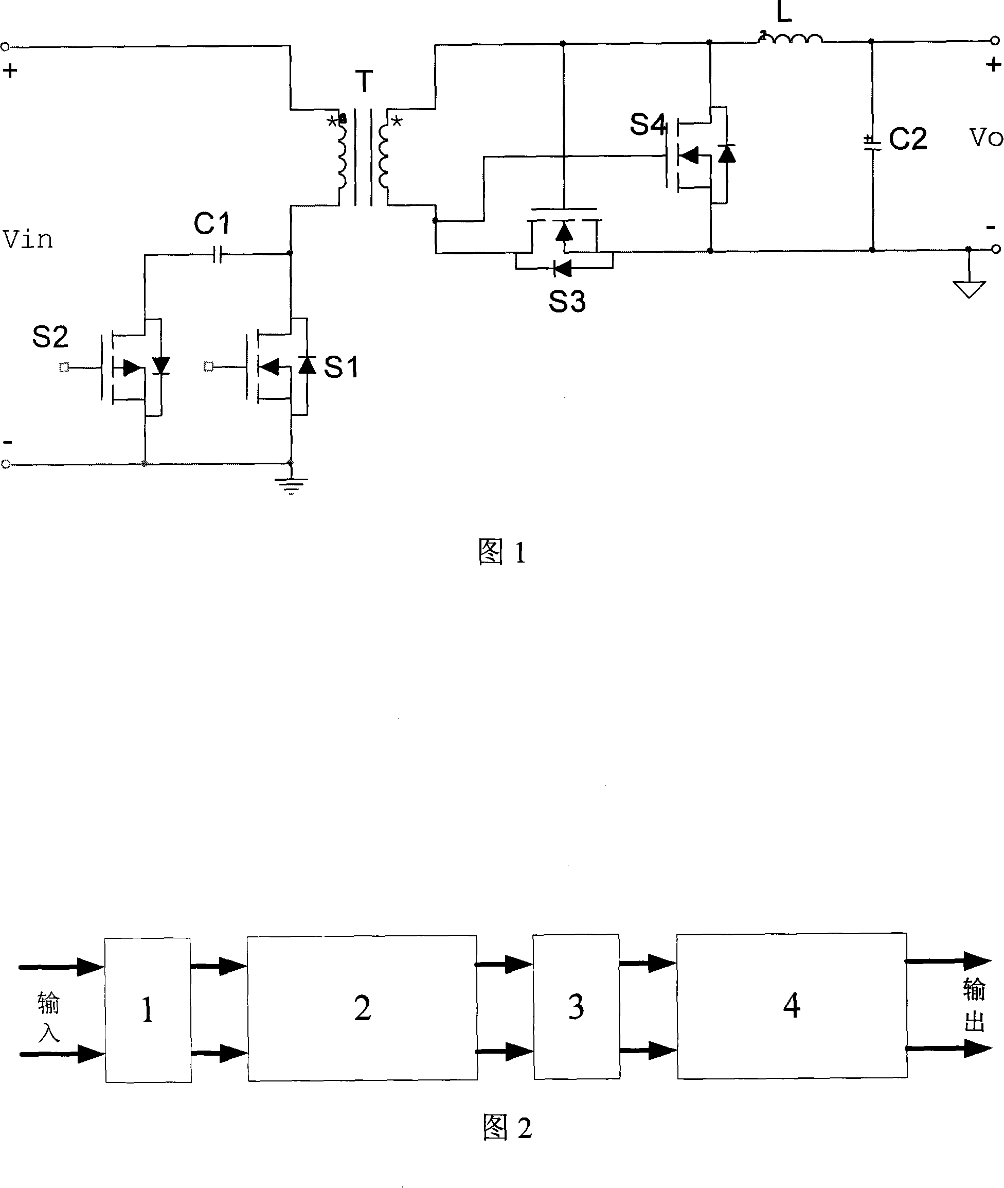
[0024] Referring to Fig. 2, a low-noise and high-efficiency power supply device includes an input common-mode filter 1, an active-clamp forward converter 2 with a self-driven synchronous rectification function, an output common-mode filter 3 and a low-dropout linear converter 4 , the input terminal of the active clamp forward converter 2 is connected to the input common-mode filter 1, the output terminal of the active clamp forward converter 2 is connected to the output common-mode filter 3, and the output terminal of the output common-mode filter 3 Connect the low dropout linear converter 4.

[0025] The input voltage first passes through the input common-mode filter 1 to filter the common-mode noise, and then passes through the active clamp forward converter 2 with self-driven synchronous rectification function to convert the input voltage to a voltage slightly higher than the required voltage It is sent to the output common-mode filter 3, which reduces the output common-mod...


PUM


Abstract

This invention discloses a power supply device including an active clamp normal shock converter with self-driving and synchronous commutation and two common-mode filters and a low voltage difference linear converter, in which, the two filters are connected to the input and output ends of the active clamp normal shock converter and the low voltage difference linear converter is connected with the common-mode filters in the following steps: the transformer in the normal shock converter is a HF plane transformer with Faraday shield, RC buffer absorption circuits are parallel between the source and the drain of the main switch tube, primary secondary non-switch nodes are connected by Y bypass capacitor and the length of a low impedance loop where the capacitor places is reduced to reduce its difference-mode noises and common-mode noises.

Description

technical field [0001] The present invention relates to a power supply device, more specifically, to a low-noise and high-efficiency power supply device. Background technique [0002] The active clamp forward converter with self-driven synchronous rectification function is a switching power supply widely used at present, as shown in Figure 1, it consists of four switching tubes S1~S4, a transformer T, two capacitors C1, C2 and Composed of inductance L, the primary winding of the transformer T is connected in series with the main switching tube S1 to form the primary main circuit; after the capacitor C1 is connected in series with the auxiliary switching tube S2, it is connected in parallel at both ends of the main switching tube S1 to form a low-end active clamping circuit; the transformer T The secondary output terminal and the synchronous rectification switch tubes S3 and S4 form a self-driven synchronous rectification circuit; the inductor L and the capacitor C2 form an o...

Claims


Application Information

Patent Timeline
IPC IPC(8): H02M1/14H02M3/335
Inventor 伊琳娜洪桂杰刘承舒晓武
Owner ZHEJIANG UNIV
Why Eureka
Try Eureka