
LTCC-based planar transformer and manufacturing method thereof

A technology for planar transformers and manufacturing methods, applied in transformers, inductance/transformer/magnet manufacturing, fixed transformers, etc., can solve the problems of limiting the performance development of planar transformers, low coupling coefficient, and inefficient flux linkage, etc., and achieve magnetic permeability improvement , high coupling coefficient, and the effect of reducing magnetic flux leakage

Inactive Publication Date: 2019-03-29
SHENZHEN SUNLORD ELECTRONICS
View PDF6 Cites 2 Cited by
  • Summary
  • Abstract
  • Description
  • Claims
  • Application Information

AI Technical Summary

Problems solved by technology

For example: the primary winding and the secondary winding are interleaved with each other, but not all the flux lines generated by the primary winding can be cut off by the secondary winding, which leads to an inefficient flux linkage between the primary winding and the secondary winding , and the flux efficiency between the primary and secondary windings is determined by the magnetic coupling coefficient
Its single magnetic permeability material structure limits the performance development of planar transformers, and there are still disadvantages such as low coupling coefficient and large leakage inductance.

Method used


Image

  • LTCC-based planar transformer and manufacturing method thereof
  • LTCC-based planar transformer and manufacturing method thereof
  • LTCC-based planar transformer and manufacturing method thereof

Examples


example

[0052] The following is an example of the LTCC planar transformer prepared by combining two LTCC materials, HP30 (permeability 30) and GTN4 (permeability 200), printed and filled by the company, and a single permeability material (HP30) LTCC planar transformer. , further verify the implementation method and conclusion of the present invention by more specific examples.

[0053] The single-permeability material LTCC planar transformer and the LTCC planar transformer of the embodiment of the present invention were respectively prepared through the above process flow, and their electrical properties were tested and compared. Its inductance and leakage inductance parameters are shown in the table below:

[0054]

[0055] It can be seen from the table that the filling of high magnetic permeability materials increases the inductance of the planar transformer by 10%-15%, and the leakage inductance is significantly improved by about 20%. Under the same inductance requirement, the ...


PUM


Abstract

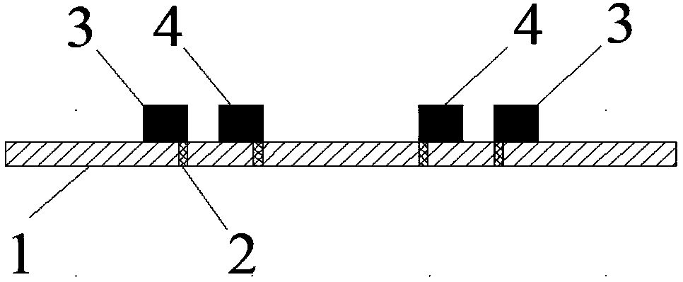
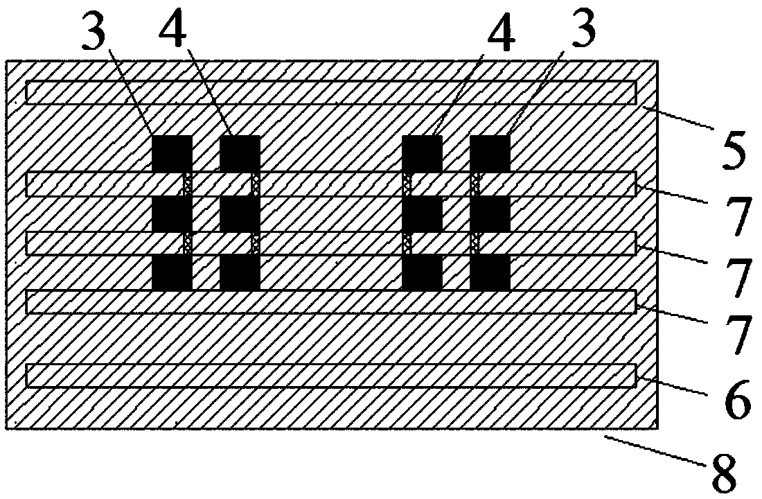
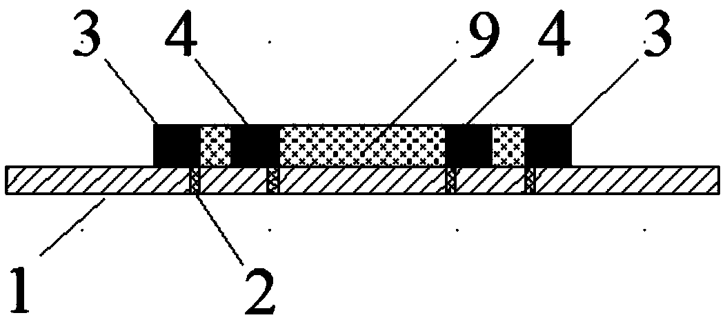
The invention discloses a LTCC-based planar transformer and a manufacturing method thereof. The method comprises the following steps: S1, preparing an upper substrate, a lower substrate and a plurality of middle substrates, which all employ an LTCC (Low Temperature Co-Fired Ceramic) material raw ceramic chip with the first magnetic conductivity; S2, forming a hole in at least one middle substrate;S3, manufacturing primary and secondary electrode patterns on the plurality of middle substrates, and performing the filling of the holes to form a plurality of electrode layers; S4, putting an LTCCmaterial with second magnetic conductivity in areas where the primary electrodes and the secondary electrodes of the plurality of electrode layers are mutually inducted and overlapped to form a plurality of filling electrode layers, wherein the second magnetic conductivity is greater than the first magnetic conductivity; S5, laminating the plurality of filling electrode layers, the upper substrateand the lower substrate, and carrying out glue discharging and sintering to form the LTCC planar transformer, in which the LTCC material with the first magnetic conductivity and the LTCC material with the second magnetic conductivity are co-fired and then tightly combined to form an intermediate magnetic conductivity material with the magnetic conductivity being between the first magnetic conductivity and the second magnetic conductivity. The coupling coefficient of a planar transformer can be effectively improved, and the primary leakage inductance and the secondary leakage inductance of theplanar transformer are reduced.

Description

technical field [0001] The invention relates to the field of LTCC (Low Temperature Co-fired Ceramic, low temperature co-fired ceramics) and laminated devices, in particular to an LTCC-based planar transformer and a manufacturing method thereof. Background technique [0002] With the development of the electronics industry, especially the technological development in the past 20 years, consumers have increasing demand for electronic products, and transformers, as an indispensable electronic component in electronic products, have huge consumer demand and market. [0003] Traditional wire-wound transformers have excellent performances such as large power and transformation ratio, but problems such as single coil structure, heat dissipation characteristics, and poor parameter consistency have been unable to meet the development trend of switching power supplies with high frequency and low cross-section. Large size is difficult to adapt to the trend of miniaturization and integra...

Claims


Application Information

Patent Timeline
IPC IPC(8): H01F41/00H01F30/06
CPCH01F30/06H01F41/00
Inventor 毛耀文陆达富王文杰
Owner SHENZHEN SUNLORD ELECTRONICS
Learn More