High-temperature planar transformer employing metal coated ceramic substrate

A technology for planar transformers and ceramic substrates, applied in transformer/inductor cores, transformer/inductor components, transformer/inductor coils/windings/connections, etc., can solve the problem of magnetic permeability reduction, metal wire width and thickness Limited, low Curie temperature, etc., to improve energy conversion efficiency, facilitate miniaturization, and improve coupling coefficient

Active Publication Date: 2018-03-13
杨杰
View PDF7 Cites 4 Cited by
  • Summary
  • Abstract
  • Description
  • Claims
  • Application Information

AI Technical Summary

Problems solved by technology

The flat enameled wire winding process has a large volume, high leakage inductance, and poor consistency; the PCB printed circuit coil has a compact structure, but it cannot work at high frequency and high temperature
The PCB printed circuit process can also be replaced by a low-temperature co-fired ceramic LTCC process to enhance high-frequency performance, but the low-temperature co-fired ceramic process is formed by printing metal paste on the green tape and co-sintering, due to the shrinkage of the metal paste and the green tape The rate is inconsistent, the printed metal wire width and thickness are limited, and cannot withstand large currents
The planar transformers used in traditional switching power supplies generally use ferrite cores. The Curie temperature is low, and the magnetic permeability decreases at high temperatures, making it unable to work normally. Drilling and other industries with high temperature environments have design requirements for high temperature and high power density of planar transformers in switching power supply modules

Method used


Image

  • High-temperature planar transformer employing metal coated ceramic substrate
  • High-temperature planar transformer employing metal coated ceramic substrate
  • High-temperature planar transformer employing metal coated ceramic substrate

Examples


Embodiment Construction

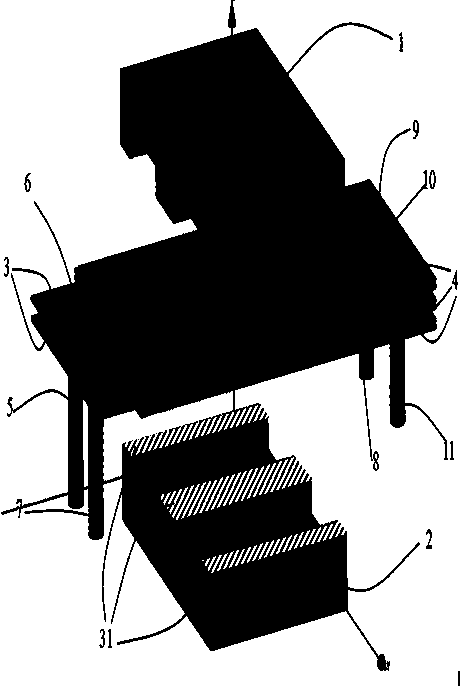
[0027] Depend on figure 2 It can be clearly seen that the examples of the high-temperature planar transformer of the present invention include: E-type iron-nickel-molybdenum metal magnetic powder cores 1 and 2 opposite to form a double-ring closed structure magnetic core; primary winding 3 and secondary winding 4. The middle part of the coil of each ceramic substrate adopts laser cutting process to process the installation hole matching the size of the middle column of the magnetic core and aligns it along the installation hole. The two parts of the magnetic core pass through the installation hole of the ceramic substrate and are bonded and fixed by the high-temperature magnetic adhesive layer 31 .

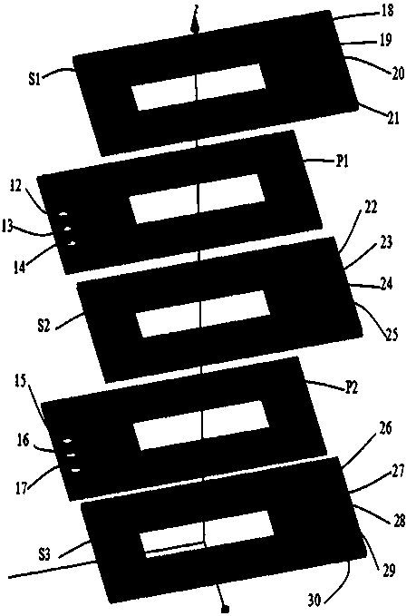
[0028] Depend on image 3 It can be seen that each transformer coil is made of metal-bonded aluminum oxide or aluminum nitride ceramic substrate 30 , and wires of a specific shape are processed on the metal layer through an etching process. According to the number of turns of ...


PUM

PropertyMeasurementUnit
Curie pointaaaaaaaaaa

Abstract

A high-temperature planar transformer employing a metal coated ceramic substrate comprises a dual-annular closed-structure magnetic core and multiple groups of ceramic substrate planar coils employinga metal coated technology, wherein the dual-annular closed-structure magnetic core is formed by splicing a group of Fe-Ni-Mo metal magnetic powder cores, all planar coil assemblies form a primary winding and a secondary winding of the transformer, an installation hole is reserved in the ceramic substrate employed by the high-temperature planar transformer and is used for placing the metal magnetic powder core material magnetic cores, and two parts of magnetic cores are placed in the installation hole from two sides of the ceramic substrate and then are abutted and pasted to a whole. Comparedwith a traditional winding transformer and a planar transformer, the high-temperature planar transformer employing the metal coated ceramic substrate has the following advantages that the power density of the transformer can be substantially improved by employing the metal coated ceramic substrate, the leakage inductance and the distributed capacitance of the transformer are reduced, the cooling efficiency is improved, moreover, the transformer can work for a long time in a high-temperature environment of 200 DEG C or above, so that the cooling design of the transformer can be simplified, thesize and the weight of the transformer are reduced, and meanwhile, the design requirement of aerospace and oil drilling in high-temperature environment industry on a switch power supply is met.

Description

technical field [0001] The invention designs a planar transformer, mainly a high-temperature planar transformer using metal bonding ceramic substrates. Background technique [0002] Traditional planar transformers mostly use flat enameled wire winding technology, PCB printed circuit technology, or a hybrid structure of the two. The flat enameled wire winding process has a large volume, high leakage inductance, and poor consistency; the PCB printed circuit coil has a compact structure, but it cannot work at high frequency and high temperature. The PCB printed circuit process can also be replaced by a low-temperature co-fired ceramic LTCC process to enhance high-frequency performance, but the low-temperature co-fired ceramic process is formed by printing metal paste on the green tape and co-sintering, due to the shrinkage of the metal paste and the green tape The rate is inconsistent, and the width and thickness of the printed metal wires are limited, which cannot withstand l...

Claims


Application Information

Patent Timeline
Patent Type & Authority Applications(China)
IPC IPC(8): H01F27/28H01F27/30H01F27/24
CPCH01F27/24H01F27/28H01F27/306H01F2027/2809H01F2027/2819
Inventor 杨杰
Owner 杨杰
Why Eureka
Try Eureka