
Coil of amorphous alloy distribution transformer

A distribution transformer and amorphous alloy technology, applied in the direction of transformer/inductor coil/winding/connection, etc., can solve the problems of poor mechanical strength of the coil, short-circuit burning, transformer discharge, etc., and achieve good coil strength and strong short-circuit resistance Effect

Inactive Publication Date: 2013-04-17
ANHUI SHENHONG TRANSFORMER
View PDF3 Cites 0 Cited by
  • Summary
  • Abstract
  • Description
  • Claims
  • Application Information

AI Technical Summary

Problems solved by technology

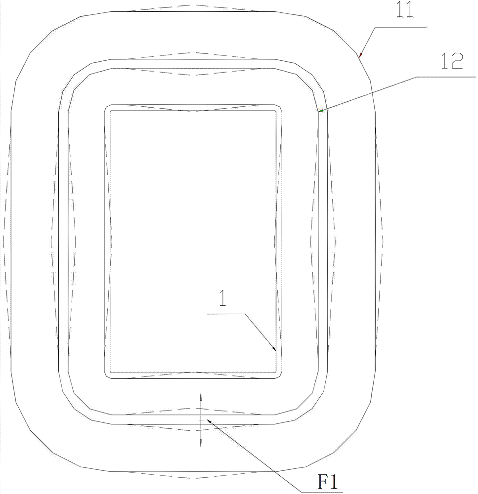
[0003] The disadvantages of this structure are: 1. The mechanical strength of the coil is poor, especially the straight part of the coil. When a short-circuit fault occurs outside the transformer, the coil will be deformed. Because there is no support inside the low-voltage coil, it will bend inward; 2. The transformer Short-circuit resistance is poor. Since the amorphous alloy material cannot bear force, the amorphous iron core is easily broken after being stressed, and the gap between the low-voltage coil and the amorphous iron core is very small. When an external short circuit occurs, the force direction of the coil (F1) As a result, the low-voltage coil bends toward the iron core side, and it is easy to transmit the short-circuit force to the amorphous iron core. After the amorphous iron core is crushed by force, the amorphous fragments will easily enter the oil and flow with the operation of the transformer oil, which will easily cause transformer damage. Discharge or even short-circuit burnt due to metal particles

Method used


Image

  • Coil of amorphous alloy distribution transformer
  • Coil of amorphous alloy distribution transformer
  • Coil of amorphous alloy distribution transformer

Examples


Embodiment Construction

[0015] In order to make the technical means, creative features, goals and effects achieved by the present invention easy to understand, the present invention will be further described below in conjunction with specific illustrations.

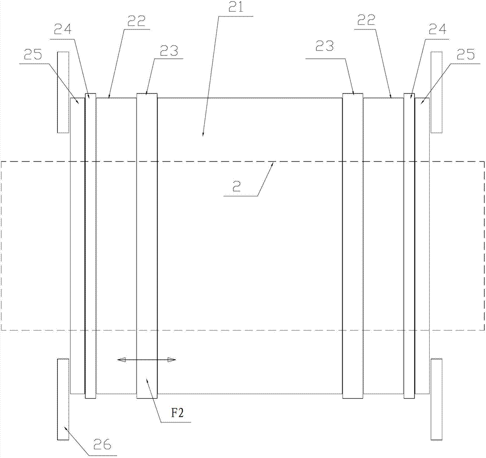
[0016] Such as figure 2 , image 3 As shown, an amorphous alloy distribution transformer coil includes an amorphous iron core 2 and a coil 27 sleeved on the amorphous iron core 2. The coil 27 is wound by a high-voltage coil 21 and a low-voltage coil 22. The high-voltage coil 21 Bundled together with the low-voltage coil 22 to form a coil 27, the high-voltage coil 21 and the low-voltage coil 22 have a rectangular structure with the same inner and outer diameters, the low-voltage coil 22 is placed on both sides of the high-voltage coil 21, and a second An insulator 23, an end plate 25 is provided on the outside of the low-voltage coil 22, the low-voltage coil 22 directly transmits the short-circuit force F2 to the end plates 25 at both ends, and...


PUM


Abstract

The invention relates to a coil of an amorphous alloy distribution transformer and relates to the technical field of transformer devices. The coil comprises an amorphous iron core and a coil body which is sleeved on the amorphous iron core, the coil body is formed by winding a high-voltage coil and low-voltage coils, and the high-voltage coil and the low-voltage coils are bundled into a whole. The coil is characterized in that the high-voltage coil and the low-voltage coils are of a rectangular structure with same internal diameters and external diameters, the low-voltage coils are placed on two sides of the high-voltage coil, first insulating parts are arranged between the low-voltage coils and the high-voltage coils, end plates are arranged on outer sides of the low-voltage coils, the low-voltage coils directly transmit short-circuit forces to the end plates at two ends, directions of the short-circuit forces are parallel to the amorphous iron core so that the short-circuit forces do not act on the amorphous iron core, second insulating parts are arranged between the end plates and the low-voltage coils, and the low-voltage coils are prevented from being deformed by being supported by the second insulating parts. The coil is high in short-circuit resisting capacity, the directions of the short-circuit forces are parallel to the amorphous iron core, the direction force which is perpendicular to the amorphous iron core is small and equals to a certain percentage of the short-circuit forces, and friction forces among the coils are enough to overcome the direction force.

Description

technical field [0001] The invention relates to the technical field of transformer equipment, in particular to an amorphous alloy power distribution transformer coil. Background technique [0002] Now the conventional amorphous alloy transformer coil structure is a concentric high and low voltage coil, that is, a concentric rectangular structure with the low voltage coil 11 inside and the high voltage coil 12 outside (see figure 1 ), the production method of this structure: wind the low-voltage wire 11 on the mold core --- place the high and low voltage insulation parts --- wind the high-voltage coil 12 --- put the coil on the amorphous core 1 on. [0003] The disadvantages of this structure are: 1. The mechanical strength of the coil is poor, especially the straight part of the coil. When a short-circuit fault occurs outside the transformer, the coil will be deformed. Because there is no support inside the low-voltage coil, it will bend inward; 2. The transformer Short-ci...

Claims


Application Information

Patent Timeline
IPC IPC(8): H01F27/30
Inventor 吴红黄遵奎吴俊付军张苏宁周明发曾咏梅吴霖
Owner ANHUI SHENHONG TRANSFORMER
Learn More