Low-bounce vacuum arc extinguish chamber structure

A technology of vacuum interrupter and cup holder, which is applied to high-voltage air circuit breakers, electrical components, electric switches, etc., can solve the problems of long bounce time, large bounce range, and overheating of the contact, so as to shorten bounce time and increase bounce range. Reduce, reduce the effect of trigger heat

Active Publication Date: 2013-04-17
中国振华电子集团宇光电工有限公司(国营第七七一厂)
View PDF6 Cites 4 Cited by
  • Summary
  • Abstract
  • Description
  • Claims
  • Application Information

AI Technical Summary

Problems solved by technology

[0003] The purpose of the present invention is to provide a low-bounce vacuum interrupter structure, which solves the problems of long bounce time, large bounce range, easy contact heating and welding phenomenon in the existing vacuum interrupter.

Method used


Image

  • Low-bounce vacuum arc extinguish chamber structure
  • Low-bounce vacuum arc extinguish chamber structure
  • Low-bounce vacuum arc extinguish chamber structure

Examples


Embodiment 1

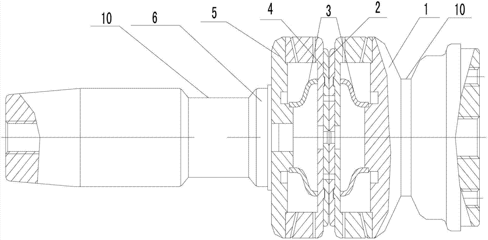
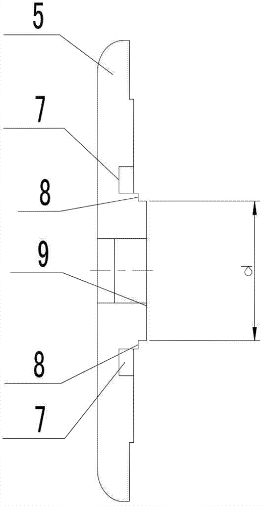
[0016] Embodiment 1 of the present invention: as attached figure 1 And attached figure 2 As shown, it includes a cup holder 5, the outer surface of the cup holder 5 is connected with the static conductive rod 1 and the movable conductive rod 6, the inner surface of the contact seat 5 is connected with the static contact 2 and the movable contact 4, and the inner surface of the cup holder 5 is connected. There is an annular groove 7 on the side, and the inner ring surrounded by the annular groove 7 is the middle stress part 9, and the middle stress part 9 surrounded by the annular groove 7 is provided with a positioning groove 8, and one end of the reinforcing rib 3 is snapped into the middle stress part 9 At the positioning groove on the top, the other end is connected with the static contact 2 and the movable contact 4, and a groove 10 is respectively provided on the static conductive rod 1 and the movable conductive rod 6.

[0017] During the closing process of the vacuum ...

Embodiment 2

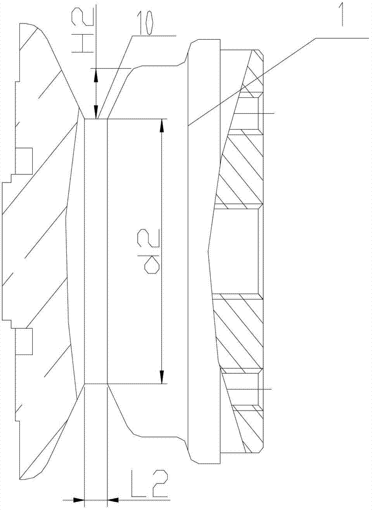
[0019] Embodiment 2 of the present invention: The structural position and working principle of the low-bounce vacuum interrupter are as described in Embodiment 1. In order to ensure that the middle stress-bearing part 9 can undergo a small amount of plastic deformation and can Ensure that its deformation will not be too large, so as to change the performance of the entire mechanism. Therefore, when opening the annular groove 7, the diameter d of the middle force-bearing part 9 can be 30mm, and the depth of the annular groove 7 is 10mm. When the groove 10 is opened, the width corresponding to the groove 10 on the moving conductive rod 6 is L1, the width corresponding to the groove 10 on the static conductive rod 1 is L2, and the range of L1 and L2 is 2 to 50 mm. The moving conductive rod 6 The depth H1 of the groove 10 on the top is 1 / 2 to 1 / 4 times of the diameter d1 of the moving conductive rod at the corresponding slot, and the depth H2 of the groove 10 on the static conducti...

Embodiment 3

[0020] Embodiment 3 of the present invention: when opening the annular groove 7, the size of the diameter d of the middle stressed part 9 can be: 45mm, and the depth of the annular groove 7 can be: 15mm. When the groove 10 is opened, the width corresponding to the groove 10 on the moving conductive rod 6 is L1, the width corresponding to the groove 10 on the static conductive rod 1 is L2, and the range of L1 and L2 is 2 to 50 mm. The moving conductive rod 6 The depth H1 of the groove 10 on the top is 1 / 3 times of the diameter d1 of the moving conductive rod at the corresponding slot, and the depth H2 of the groove 10 on the static conductive rod 1 is 1 times the diameter d2 of the static conductive rod at the corresponding slot. / 3 times.


PUM


Abstract

The invention discloses a low-bounce vacuum arc extinguish chamber structure. The low-bounce vacuum arc extinguish chamber structure is characterized by comprising a cup saucer (5), wherein the inner side of the cup saucer (5) is connected with a static contact (2) and a moving contact (4); an annular groove (7) is formed in the inner side connected with the cup saucer (5); an inner ring surrounded by the annular groove (7) is a middle stress part (9); and one end of each reinforcing rib (3) is connected with the middle stress part (9) on the cup saucer (5). According to the low-bounce vacuum arc extinguish chamber structure, the pressure intensity is increased by changing the stress area under the condition that the pressure is not changed; a workpiece is impelled to generate tiny plastic deformation due to the effect of high pressure intensity, so that the acting force is absorbed and removed; and the acting force is reduced, so that shorten bouncing time is shortened, the bouncing amplitude is reduced, the probability of contact heating or fusion welding is reduced, aggravation of electric wear of the contact is avoided, and the service life of the vacuum arc extinguish chamber is prolonged.

Description

technical field [0001] The invention relates to a structure of a low-bounce vacuum interrupter, which belongs to the technical field of electric switchgear. Background technique [0002] During the closing process of the vacuum interrupter, the moving contact and the static contact of the vacuum interrupter are just in contact until the moment when the contacts are in stable contact. During this period, there will be repeated opening and closing processes of the moving contact and the static contact. That is, the bouncing phenomenon. During the closing process of the currently used vacuum interrupter, the two contacts bounce due to rigid collision. The bounce time is long and the bounce range is large, which cannot meet the mechanical parameter requirements of the vacuum circuit breaker. This bouncing phenomenon not only affects the stability and reliability of the vacuum interrupter, but also in the closing process, because the distance between the moving contact and the s...

Claims


Application Information

Patent Timeline
Patent Type & Authority Applications(China)
IPC IPC(8): H01H33/664
Inventor 张毅陈志会周吉冰
Owner 中国振华电子集团宇光电工有限公司(国营第七七一厂)
Why Eureka
Try Eureka