Axial-segmented solid permanent-magnet rotor

A technology of axially segmented and permanent magnet rotors, applied in the direction of magnetic circuit rotating parts, magnetic circuit shape/style/structure, etc., can solve the problems of poor ventilation, high temperature, irreversible demagnetization of permanent magnets, etc., and achieve simple structure , improve the service life and high practicability

Active Publication Date: 2013-04-17
HARBIN UNIV OF SCI & TECH
View PDF4 Cites 20 Cited by
  • Summary
  • Abstract
  • Description
  • Claims
  • Application Information

AI Technical Summary

Problems solved by technology

[0003] The present invention aims to solve the problem of irreversible demagnetization of the permanent magnet caused by the high temperature of the existing solid rotor of the permanent magnet motor due to poor ventilation, and provides an axially segmented solid permanent magnet rotor

Method used


Image

  • Axial-segmented solid permanent-magnet rotor
  • Axial-segmented solid permanent-magnet rotor

Examples


specific Embodiment approach 1

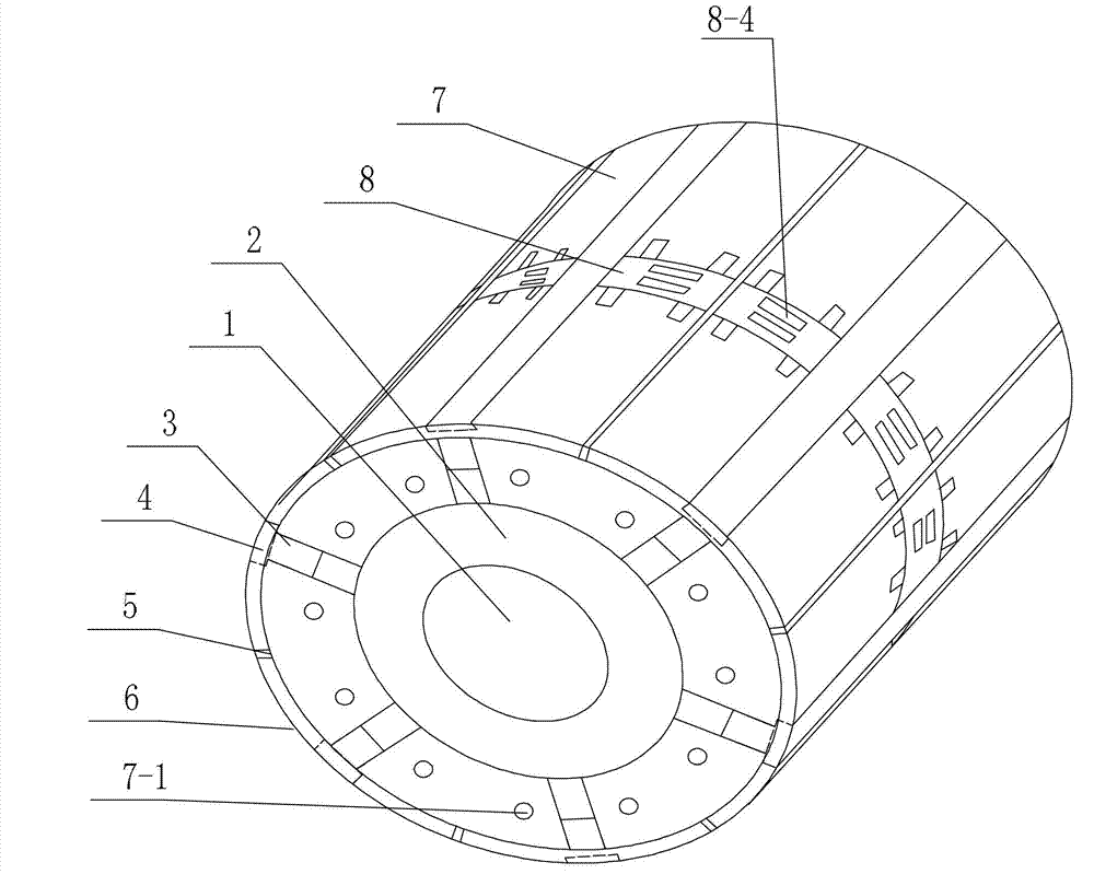
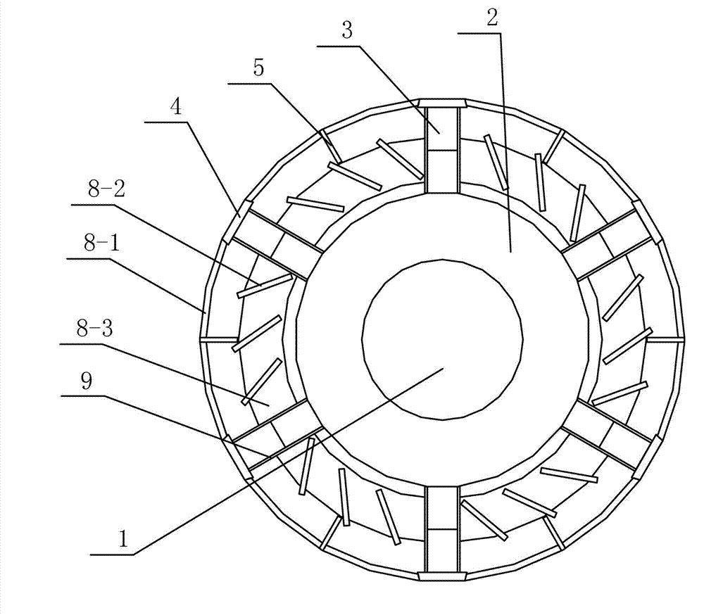
[0021] Specific implementation mode one: the following combination figure 1 and figure 2 Describe this embodiment, the axially segmented solid permanent magnet rotor described in this embodiment includes a rotating shaft 1, and it also includes a magnetic isolation ring 2, a plurality of permanent magnets 3, a plurality of permanent magnet slot wedges 4, and a plurality of starting magnets. Cage bars 5, two cage bar end rings 6, two rotor axial segments 7 and air guides 8, the number of permanent magnets 3, permanent magnet slot wedges 4 and starting cage bars 5 is the same, and the two rotor shafts To the same structure as segment 7,

[0022] The magnetic isolation ring 2 is sleeved on the outer circular surface of the rotating shaft 1, the two rotor axial segments 7 are axially sleeved on the outer circular surface of the magnetic isolation ring 2, and the two rotor axial segments 7 pass through The air guiding parts 8 are connected together,

[0023] Each rotor axial se...

specific Embodiment approach 2

[0034] Specific implementation mode two: the following combination figure 1 and figure 2 Describe this embodiment. This embodiment is a further description of Embodiment 1. Two rectangular ventilation holes 8-4 are provided on the upper connecting ring section 8-1, and the two rectangular ventilation holes 8-4 are arranged along the axial direction. arrangement.

specific Embodiment approach 3

[0035] Embodiment 3: This embodiment is a further description of Embodiment 1 or 2. An insulating plate 9 is provided between the contact surfaces of the permanent magnet 3 and the circumferential segment of the rotor.

[0036] The arrangement of the insulating plate can prevent the permanent magnet 3 from running in series when the motor is running.


PUM


Abstract

The invention relates to an axial-segmented solid permanent-magnet rotor, belonging to the technical field of motors. The axial-segmented solid permanent-magnet rotor is used for solving the problem that permanent magnets are subjected to irreversible demagnetization due to too-high temperature due to the fact that the existing solid rotor of a permanent-magnet motor can not be subjected to good ventilation. The axial-segmented solid permanent-magnet rotor comprises a rotary shaft, a magnetism isolating ring, a plurality of permanent magnets, a plurality of permanent magnet slot wedges, a plurality of starting cage strips, two cage strip end rings, two axial rotor segments and an air guide portion, wherein the permanent magnets, the permanent magnet slot wedges and the starting cage strips are the same in number, the two axial rotor segments are same in structure, the magnetism isolating ring is sleeved on the external circular surface of the rotary shaft, the two axial rotor segments are sleeved on the external circular surface of the magnetism isolating ring along the axial direction and connected together through the air guide portion, each axial rotor segment is equally divided into a plurality of circumferential rotor segments along the circumferential direction, and a permanent magnet slot is formed between every two adjacent circumferential rotor segments along the circumferential direction. The axial-segmented solid permanent-magnet rotor is suitable for motor solid rotors.

Description

technical field [0001] The invention relates to an axially segmented solid permanent magnet rotor and belongs to the technical field of motors. Background technique [0002] Solid rotor permanent magnet synchronous motors have good starting performance, are suitable for heavy-duty starting, have high efficiency and power factor, and are widely used in electric power, chemical industry, petrochemical, steel, water conservancy, building materials and other occasions that require high performance. If the solid rotor does not adopt a certain ventilation structure, the heat generated by the eddy current loss on its surface will cause the temperature rise of the entire rotor to be too high, and the performance of the permanent magnet will decrease with the increase of temperature, thereby reducing the performance of the motor. The maximum allowable operating temperature of the magnet may cause irreversible demagnetization of the permanent magnet. Once it occurs, the permanent magn...

Claims


Application Information

Patent Timeline
Patent Type & Authority Applications(China)
IPC IPC(8): H02K1/27H02K1/32
Inventor 李伟力张晓晨曹君慈陈辰李金阳沈稼丰黄东洙
Owner HARBIN UNIV OF SCI & TECH
Why Eureka
Try Eureka