Tuning circuit and tuning method of on-chip filter

A tuning circuit and filter technology, applied in the direction of frequency selection two-terminal pair network, multi-terminal pair network, etc., can solve the problem that frequency tuning and Q value tuning cannot be realized at the same time

Active Publication Date: 2013-04-17
广州润芯信息技术有限公司
View PDF3 Cites 7 Cited by
  • Summary
  • Abstract
  • Description
  • Claims
  • Application Information

AI Technical Summary

Problems solved by technology

[0005] The advantages and disadvantages of indirect tuning and direct tuning methods are: indirect tuning can adjust filter parameters in real time without hindering signal transmission; while direct tuning needs to tune the filter when signal transmission is idle, that is to say, direct tuning requires

Method used


Image

  • Tuning circuit and tuning method of on-chip filter
  • Tuning circuit and tuning method of on-chip filter
  • Tuning circuit and tuning method of on-chip filter

Examples


Embodiment 1

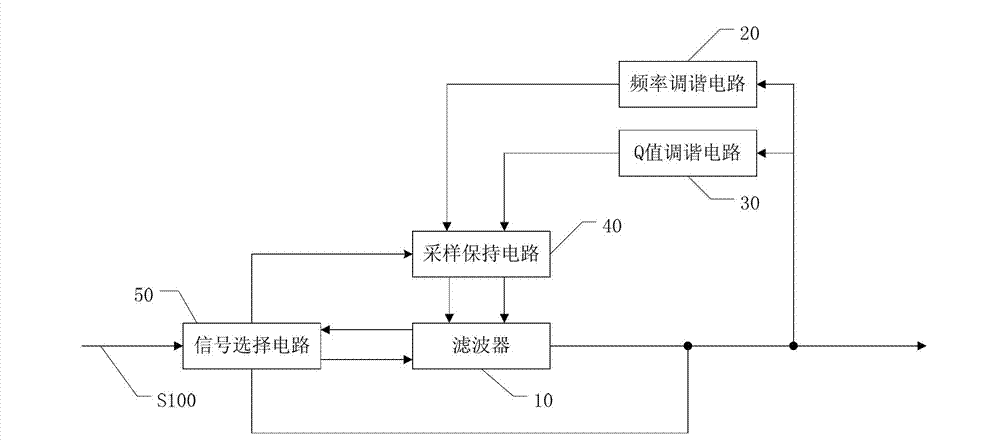
[0070] like figure 1 As shown, an on-chip filter tuning circuit includes a filter 10 , a signal selection circuit 50 , a Q value tuning circuit 30 , a sample-and-hold circuit 40 and a frequency tuning circuit 20 .

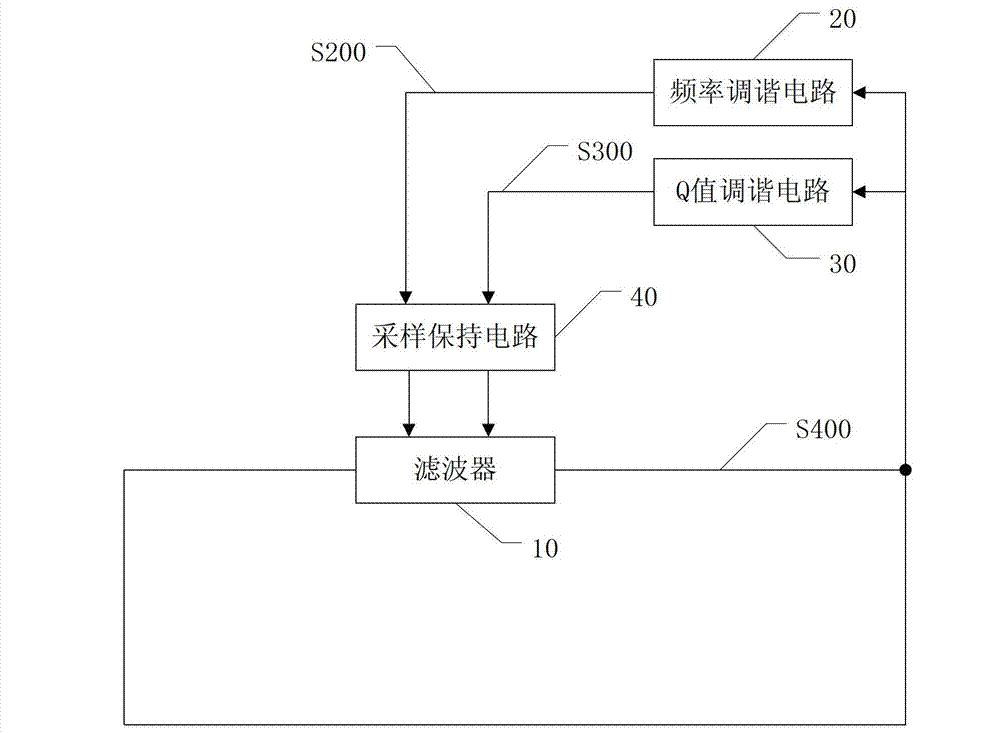
[0071] The signal selection circuit 50 of this embodiment may be composed of a plurality of signal selection switches and a control logic for controlling the opening and closing of the signal selection switches. The signal selection circuit 50 is used for disconnecting the signal input terminal (not shown in the figure) of the filter 10 from the input signal S100 when the filter 10 is idle, and disconnecting the signal input terminal of the filter 10 from the signal output terminal (not shown in the figure) Marked) connection, the frequency tuning circuit 20, the Q value tuning circuit 30 are respectively connected to the sample and hold circuit 40, such as figure 2 Shown, so that filter 10, Q value tuning circuit 30, sample and hold circuit 40 form the first tu...

Embodiment 2

[0099] Embodiment 1 is applicable to a filter with an output gain of 0 dB. However, this embodiment is applicable to filters whose output gain is not 0 dB. like Figure 9 As shown, the difference between this embodiment and Embodiment 1 is that a gain compensation module is added. details as follows:

[0100] When tuning (that is, when the filter is idle), the signal selection circuit disconnects the signal input terminal of the filter 10 from the input signal, connects the signal input terminal of the filter 10 to the signal output terminal through a gain compensation module, and tunes the frequency Circuit 20, Q value tuning circuit 30 are connected with sample and hold circuit 40 respectively, so that filter 10, Q value tuning circuit 30, sample and hold circuit 40 form the first tuning loop, filter 10, frequency tuning circuit 20, sample and hold Circuit 40 forms a second tuned loop.

[0101] The gain compensation module is used to adjust the output gain of the filter ...


PUM


Abstract

The invention relates to a tuning circuit and a tuning method of an on-chip filter. According to the tuning circuit and the tuning method, through inherent frequency phase response characteristics of the filter, the filter is connected into a closed loop in spare time, so as to perform self-excited oscillation, the frequency and the amplitude value of the self-excited oscillation of the filter are detected, and parameters of the filter are adjusted, so as to tune the frequency and the Q value of the filter. The tuning circuit has the advantages of simple structure and easiness in implementation, the influence of a conformity error and layout design of the CMOS (Complementary Metal Oxide Semiconductor) process on the tuning result of the filter is less, and the frequency and Q value tuning functions of the on-chip filter can be implemented at the same time.

Description

technical field [0001] The invention relates to a direct tuning circuit and a direct tuning method of a filter. Background technique [0002] At present, filters have been widely integrated on CMOS chips (complementary metal oxide semiconductors) to provide filtering functions. Different from discrete components, due to the influence of integrated circuit process deviation, layout design, and temperature changes, the original parameters of the on-chip integrated filter deviate greatly from the design value, and need to be tuned to achieve low-pass, high-pass, and band-pass within a certain frequency range. Or band-stop and other frequency characteristics. [0003] The current tuning methods are generally divided into two types: direct tuning and indirect tuning. Indirect tuning is to design a slave module similar to the filter structure, such as the tuning system structure of the master-slave filter or filter oscillator. Detect the input and output signals of the slave mod...

Claims


Application Information

Patent Timeline
IPC IPC(8): H03H11/08H03H11/12
Inventor 胡思静刘渭陈红林王明照张丽娟王祥炜符卓剑张弓杨寒冰李正平石磊
Owner 广州润芯信息技术有限公司
Why Eureka
Try Eureka