A centrifugal separator

A technology for centrifugal separators and conveyors, applied in centrifuges, centrifuges with rotating drums, etc., can solve the problems of increased energy, complexity, and difficulty in discharging hard solid blocks of screw conveyors, and achieve reduction effect of weight

Inactive Publication Date: 2013-04-17
ALFA LAVAL CORP AB
View PDF12 Cites 4 Cited by
  • Summary
  • Abstract
  • Description
  • Claims
  • Application Information

AI Technical Summary

Problems solved by technology

These tiles are made of relatively expensive wear resistant material and attaching them all to the edges of the conveyor auger can be very complex and time consuming which in turn will increase the overall production cost of the auger
In addition, utilizing relatively high density wear-resistant materials (e.g., approximately 13-16 g/cm 3 Tungsten carbide) and arrangin

Method used


Image

  • A centrifugal separator
  • A centrifugal separator
  • A centrifugal separator

Examples


Embodiment Construction

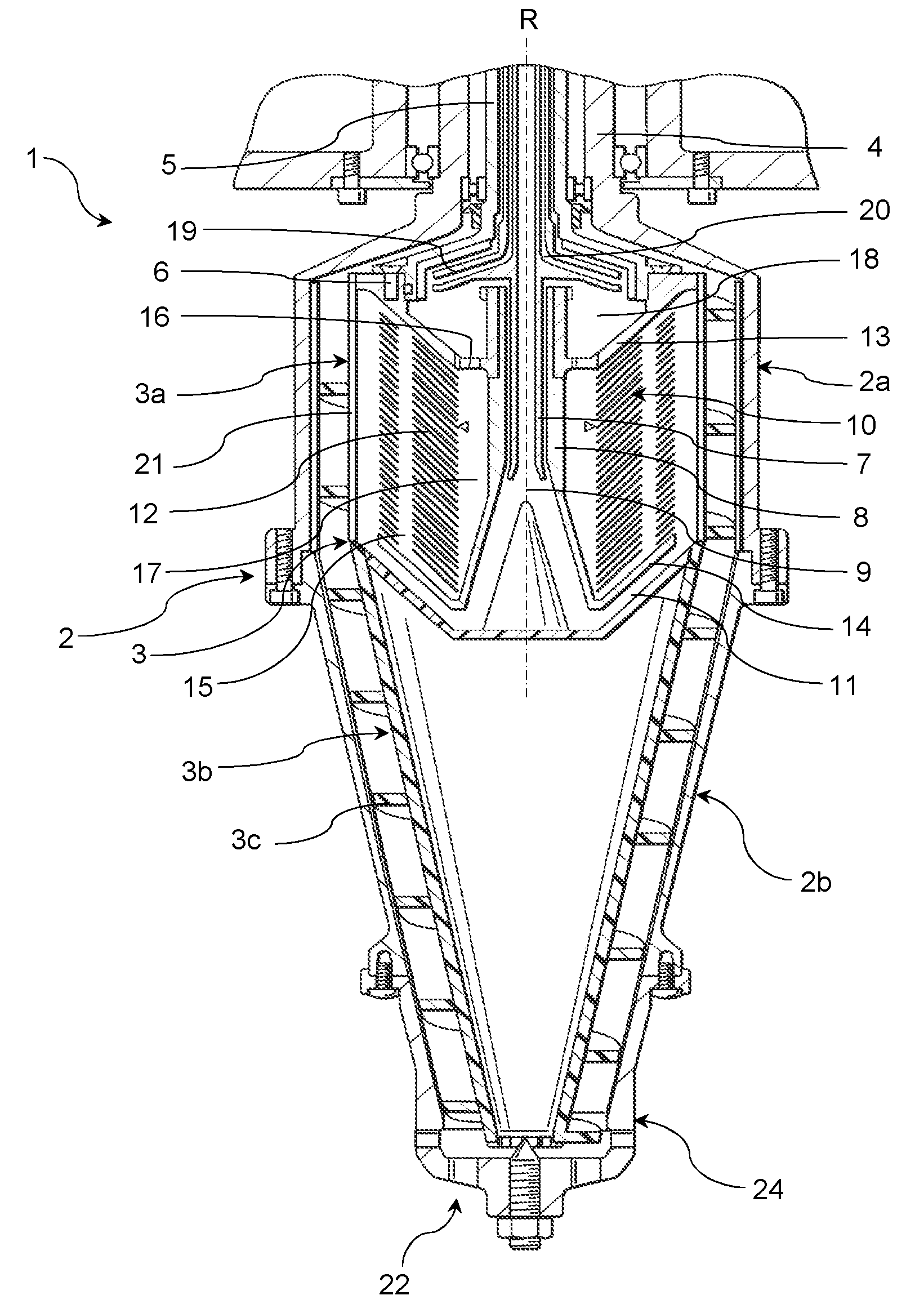
[0026] figure 1 A centrifugal separator 1 according to an embodiment of the invention is shown. The centrifugal separator 1 comprises: a rotor 2 which can rotate at a certain speed about a vertical axis of rotation R; The rotation speed is the speed at which to rotate.

[0027] The centrifugal separator 1 is intended to be suspended vertically in the manner indicated by WO 99 / 65610 A1. The means required to suspend and drive the centrifugal separator 1 are therefore not described here.

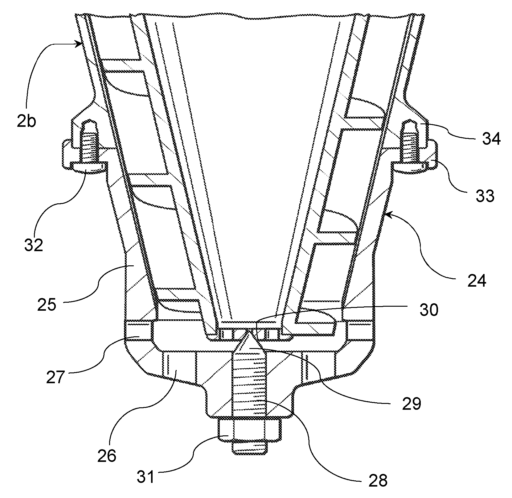
[0028] The rotor 2 has a substantially cylindrical upper rotor part 2a and a substantially conical lower rotor part 2b, the rotor parts 2a and 2b being connected to each other by screws. Optional connection parts can of course be used. The cylindrical rotor part 2a comprises an axially upward extension in the form of a hollow rotor shaft 4 which is connected to drive means (not shown) for rotating the rotor 2 about an axis R of rotation.

[0029] A further hollow shaft 5 extends through t...


PUM


Abstract

The present invention relates to a centrifugal separator (1) comprising a rotor (2) which is rotatable around an axis of rotation (R), the rotor (2) comprising a separation chamber (10) with an inlet (7, 9, 11) for a liquid mixture containing solid particles, at least one liquid outlet (18, 19, 20) for a separated liquid from the liquid mixture, and a solids outlet (22, 26, 27) for the separated solid particles, wherein a screw conveyor (3) is arranged to rotate inside the rotor (2) around the axis of rotation (R), at a different speed than the rotor (2), the screw conveyor (3) having at least one conveyor flight (3c) for transporting the separated solid particles in the separation chamber (10) towards and out of the solids outlet (22), wherein the conveyor flight (3c) is provided with wear resistant elements (23) arranged along its edge and the wear resistant elements (23); are spaced apart with an interspace (23a) between mutually adjacent wear resistant elements (23).

Description

technical field [0001] The invention relates to a centrifugal separator comprising: a rotor rotatable about an axis of rotation, the rotor comprising a separation chamber with an inlet for a liquid mixture containing solid particles; at least one liquid for separating liquid from the liquid mixture an outlet; and a solids outlet for separating solid particles, a screw conveyor arranged to rotate within the rotor about an axis of rotation at a speed different from that of the rotor, the screw conveyor having at least one conveyor flight for facing the solids outlet in the rotor Conveying the separated solid particles and transporting them out of the solids outlet, the conveyor flight is provided with anti-wear elements arranged along its edges. [0002] A general problem associated with this type of centrifugal separator is that the conveyor flight(s) can wear away rapidly as the separated solids are very abrasive. Such separated solids will under certain conditions form a har...

Claims


Application Information

Patent Timeline
IPC IPC(8): B04B1/20B04B7/12
CPCB04B1/2008B04B2001/2066B04B1/20B04B7/12
Inventor J.郑C.瓦泽R.里德施塔拉勒
Owner ALFA LAVAL CORP AB
Why Eureka
Try Eureka