Stirring system

A technology of stirring system and stirring rack, which is applied in the direction of mixer accessories, dissolving, mixing machines, etc., can solve the problems of low mixing efficiency, hard raw material texture, wear, etc., and achieve the effect of preventing aggravated wear, prolonging service life and improving quality

Active Publication Date: 2014-12-10
ZHEJIANG ROXZ ELECTRIC CO LTD
View PDF6 Cites 0 Cited by
  • Summary
  • Abstract
  • Description
  • Claims
  • Application Information

AI Technical Summary

Problems solved by technology

[0004] Although the above-mentioned stirring system can realize the stirring of raw materials, there are still big problems in the actual use process: 1. Because the distance between the feed inlet and the transmission shaft is relatively close, and the upper end of the transmission shaft is exposed outside, so, When putting powdery raw materials into the material tank or drawing air from the upper side of the transmission shaft during the mixing process, the powdery raw materials will be lifted up and enter the joint between the transmission shaft and the mounting plate, causing the transmission When the shaft rotates relative to the mounting plate, the wear will be aggravated due to the relationship between the two materials; , in the process of use, there will be shaking between the two due to wear, but there is only one bearing between the transmission shaft and the mounting plate to limit the position of the transmission shaft, so when the transmission shaft shakes, its outer wall will be in contact with the installation plate. The friction between the mounting plate or other parts will cause the outer surface of the transmission shaft to wear into metal powder and fall into the material tank along the connection gap between the transmission shaft and the mounting plate, affecting the quality of the raw material mixture after stirring; 3. When the ambient temperature is low, the texture of the raw materials is hard, it is difficult to mix during the stirring process, and the mixing efficiency is low

Method used


Image

  • Stirring system
  • Stirring system

Examples


Embodiment Construction

[0026] The following are specific embodiments of the present invention and in conjunction with the accompanying drawings, the technical solutions of the present invention are further described, but the present invention is not limited to these embodiments.

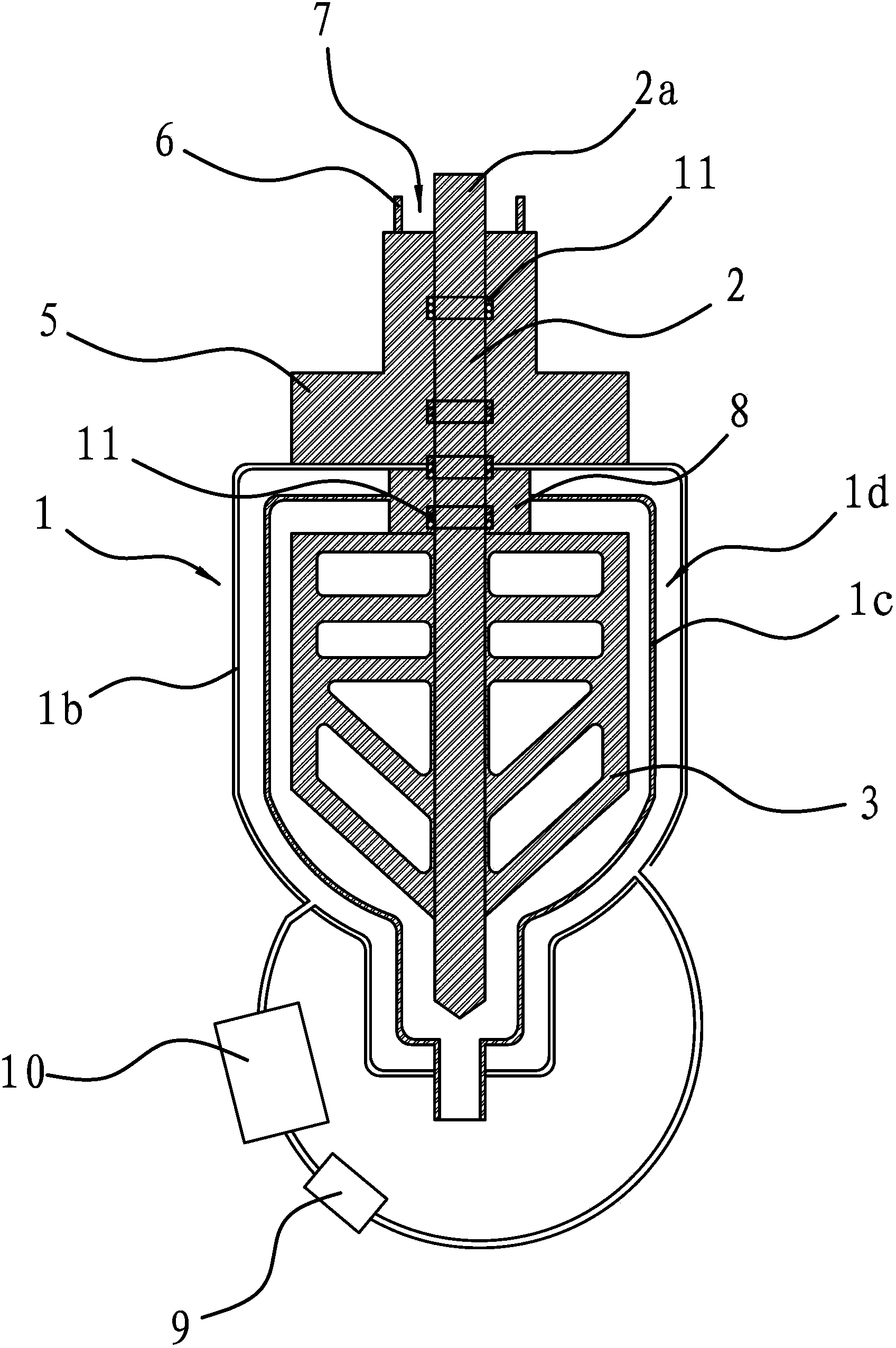
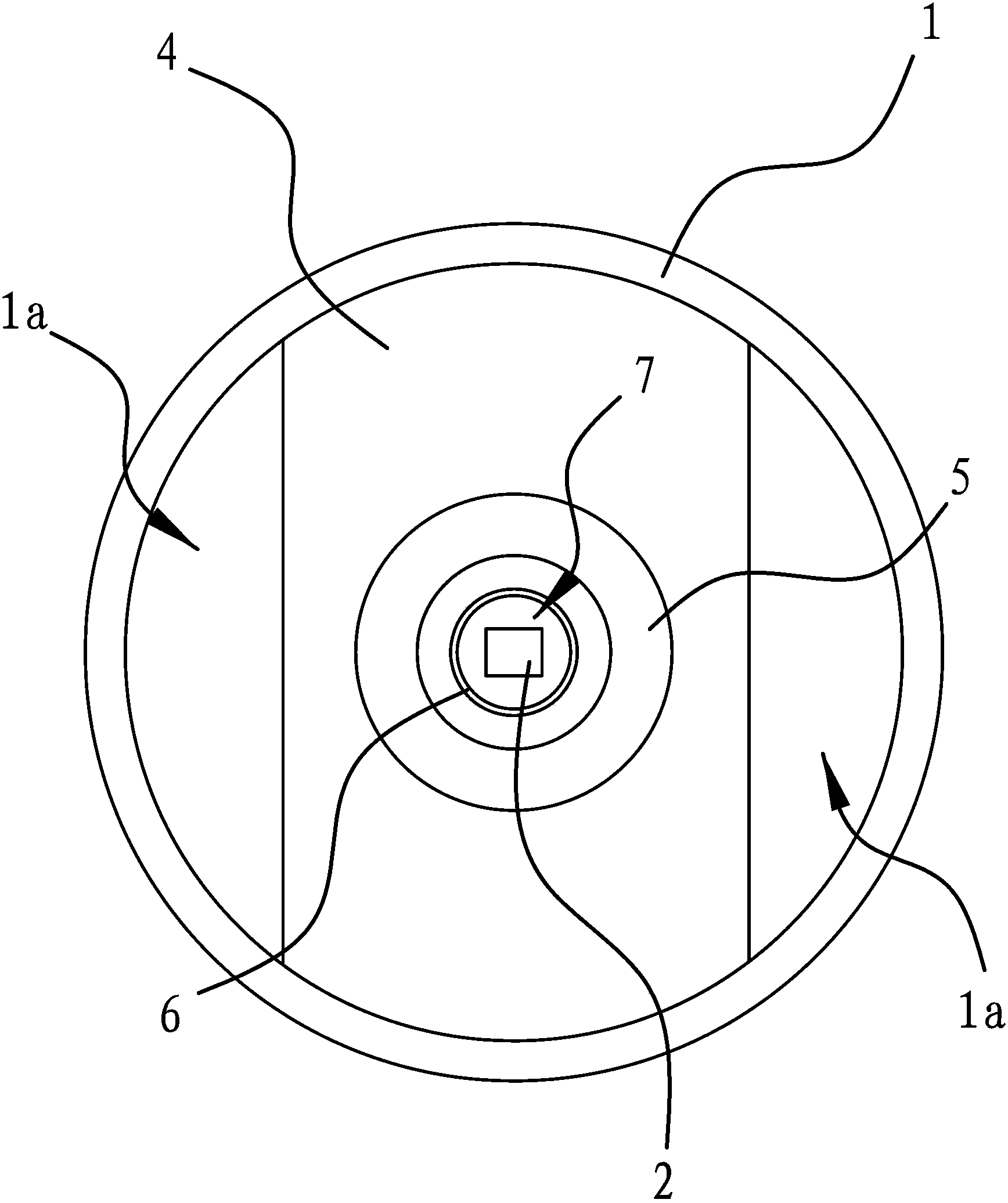
[0027] Such as figure 1 , figure 2 As shown, the stirring system includes a cylindrical material tank 1 with an opening at the upper end, a vertically arranged transmission shaft 2 and a stirring frame 3, and a horizontally arranged mounting plate 4 is fixedly connected to the opening at the upper end of the material tank 1. The mounting plate 4 is connected to the middle part of the opening of the material tank 1 and forms two feed inlets 1 a for feeding between it and the side wall at the upper end of the material tank 1 . The upper side and the lower side of the mounting plate 4 are fixedly connected with the mounting seat 5 and the fixing seat 8 respectively, and the lower end of the transmission shaft 2 passes throu...


PUM


Abstract

The invention provides a stirring system and belongs to the technical field of a machine. The problems in the conventional stirring system that the abrasion is severe, the quality is low after a raw material is stirred, and the mixing efficiency is low in a low-temperature environment can be solved. The stirring system comprises a cylindrical material tank with an opening at the upper end, a vertically-arranged transmission shaft and a stirring frame; a mounting board is fixedly connected at the opening of the material tank; a feeding opening is formed between the mounting board and the lateral wall of the upper end of the material tank; a mounting base is further fixedly connected with the upper side of the mounting board; the transmission shaft is arranged inside the mounting base and the mounting board in a penetrating manner; the lower end of the transmission shaft is fixedly connected with the circumference direction of the stirring frame by means of penetrating through the mounting board, and the upper end of the transmission shaft extends out from the upper side of the mounting base; a connection part which is fixedly connected with the circumference direction of driving equipment is arranged at the extending position; a cylindrical isolation piece is further arranged on the upper side of the mounting base around an axis of the transmission shaft; and an annular concave cavity is arranged between the isolation piece and the transmission shaft. The stirring system has the advantages of long service life, high quality after the raw material is stirred, and high stirring efficiency at the low temperature.

Description

technical field [0001] The invention belongs to the technical field of machinery and relates to a stirring system. Background technique [0002] The mixing system refers to a machine in which a shaft with blades rotates in a cylinder or a tank to stir and mix various raw materials to form a mixture or a suitable consistency. Among them, the mixing system that has higher requirements on the stirred mixture also needs to extract the air in the cylindrical material tank where the raw materials are placed during the stirring process. [0003] The existing mixing system includes a cylindrical and vertically arranged material tank, a mounting plate fixedly connected to the upper end of the material tank, a transmission shaft vertically pierced on the mounting plate, and a Bearings and a stirring frame fixed to the lower end of the transmission shaft for stirring raw materials. Wherein, the lower end of the material tank is closed and the upper end is open, the mounting plate is ...

Claims


Application Information

Patent Timeline
Patent Type & Authority Patents(China)
IPC IPC(8): B01F15/00B01F15/06
Inventor 张云根
Owner ZHEJIANG ROXZ ELECTRIC CO LTD
Why Eureka
Try Eureka