Anti-torsion steel bar feeding mechanism

A feeding mechanism and steel bar technology, which is applied in the field of torsion-resistant steel bar feeding mechanism, can solve the problems of pressure crushing on the surface of steel bars, torsion and rolling of steel bars, and easy rotation, etc., so as to increase the contact area of ​​compression and improve the quality of finished steel bars Good quality and traction effect

Active Publication Date: 2014-12-10
TJK MACHINERY TIANJIN
View PDF5 Cites 6 Cited by
  • Summary
  • Abstract
  • Description
  • Claims
  • Application Information

AI Technical Summary

Problems solved by technology

[0004] There are the following defects in adopting the prior art steel bar traction mechanism and straightening mechanism to convey straightened ribbed steel bars: first, when two ribbed steel bars pass between the main drive wheel and the pressure wheel of the traction mechanism at the same time, due to the ribbed steel bar section It is elliptical, and there is a difference in the cross-sectional shape of the two steel bars that enter between the main drive wheel and the pressure wheel at the same time. The same pressure wheel cannot be pressed on two steel bars at the same time, and the pressure on the two steel bars is inconsistent. When the pressing force of the pressing wheel is high, one of the steel bars will be over-pressed and the surface of the steel bar will be damaged, and the steel bar with low pressure will appear torsion, rolling and slipping. The existing technology of the pressing wheel mechanism is difficult to ensure that the two steel bars are driven evenly and stably at the same time. force
Secondly, the feeding mechanism of the prior art adopts a main drive wheel corresponding to a pressing wheel, and the steel bar passes through the tangential direction of the main driving wheel and the pressing wheel, the contact area between the steel bar and the driving wheel is small, the friction force is small, and the traction speed is slow
In addition, the forward direction of the pulled steel bar is a straight line, and it is prone to self-rotation during the feeding process. There is a deformation defect that the bent stirrups have several sides that are not in the same plane due to the torsion of the steel bar during the feeding process.

Method used


Image

  • Anti-torsion steel bar feeding mechanism
  • Anti-torsion steel bar feeding mechanism
  • Anti-torsion steel bar feeding mechanism

Examples


Embodiment Construction

[0015] Embodiments of the present invention are described in further detail below in conjunction with the accompanying drawings:

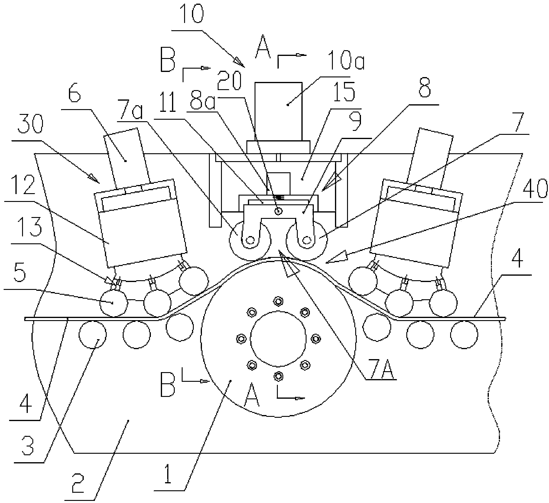
[0016] As shown in the figure, the present invention provides an anti-twist type steel bar feeding mechanism, and the anti-twist type steel bar feeding mechanism includes: a frame 2, a traction mechanism 40 arranged on the frame 2 and a structure with the same position and symmetrical Two straightening wheel sets 30 of.

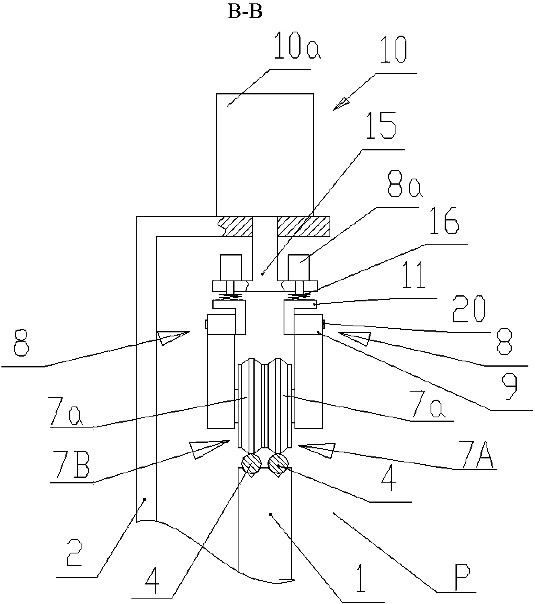
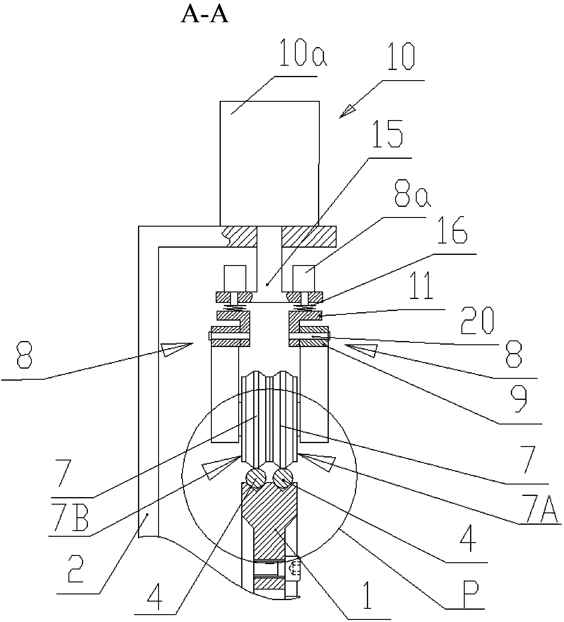
[0017] The traction mechanism 40 is arranged between the two straightening wheel sets 30, and its position is higher than the two straightening wheel sets 30 on both sides; the traction mechanism 40 includes: the main driving wheel 1 and the main driving wheel 1 The pressure roller above; the V-shaped groove of the traction steel bar 4 is arranged on the outer edge of the main driving wheel 1, and one end of the main driving wheel 1 is connected to a rotating power source (not shown in the figure), and the rotating power source is...


PUM


Abstract

The invention discloses an anti-torsion steel bar feeding mechanism, which comprises a frame and two straightening wheel sets, wherein a traction mechanism is arranged between the two straightening wheel sets and is higher than the two straightening wheel sets; the traction mechanism comprises a main drive wheel and a pressing wheel; a steel bar traction V-shaped groove is formed in the outer edge of the main drive wheel; the outer edge of the cross section of the pressing wheel is outwardly projected ladder-shaped; the pressing wheel is arranged on a pressing mechanism; the pressing mechanism is arranged on the frame; the two straightening wheel sets comprise a plurality of straightening wheels and straightening wheel pressing mechanisms respectively; a trailed steel bar wound on the main drive wheel is pressed to be arc-shaped by the straightening wheels; and the pressing wheel is used for pressing the arc-shaped steel bar. The anti-torsion steel bar feeding mechanism has the beneficial effects that the steel bar is contacted with the arc surface of the main drive wheel, the pressure contact area of the steel bar and the main drive wheel is large, the steel bar is not twisted, and the traction effect is good; and the pressing wheel can be used for tightly pressing the steel bar to prevent slip, rib damage, torsion and asynchronous defect of the steel bar and improve the quality of the finished steel bar. A plurality of steel bars are good in synchronicity, simple in structure and convenient to repair.

Description

technical field [0001] The invention relates to a steel bar feeding mechanism, in particular to a torsion-resistant steel bar feeding mechanism. Background technique [0002] At present, in the production and processing of various steel bars in the construction industry, it is usually necessary to straighten the raw material wire rods and steel bars and then transport them to the processing equipment for further processing. Before the steel bars are sent to the deep processing equipment, the steel bars need to be pulled Mechanism for conveying, and then the straightening mechanism will process the bent steel bars into straight steel bars. [0003] The traction mechanism in the prior art includes: a main driving wheel connected with a motor and a pressure wheel located above the main driving wheel, and the wire rod is pulled and moved between the main driving wheel and the pressure wheel by friction. In order to improve the pulling efficiency of the prior art steel bars, two...

Claims


Application Information

Patent Timeline
Patent Type & Authority Patents(China)
IPC IPC(8): B21F1/02B21F23/00
Inventor 陈振东
Owner TJK MACHINERY TIANJIN
Why Eureka
Try Eureka